After the edge transition, the status of the inputs is stored here. The
input byte has the following bit assignments:
Bit 0: DI 0
Bit 1: DI 1
Bit 2: DI 2
Bit 3: DI 3
Bit 4 … 7: reserved (0)
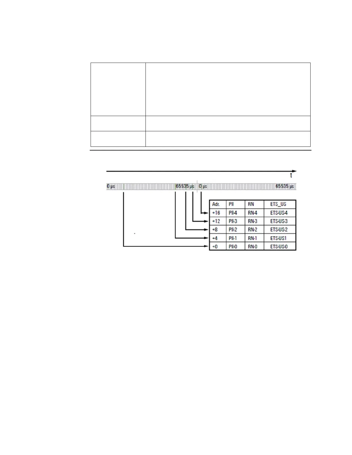
The RN (running number) is a consecutive number from 0 to 127. It
describes the chronological sequence of the edges
The 16-bit timer (0 ... 65,535
μ
s) in the RSTi-EP module is started as soon
as the power supply is switched on and after (216 -1)
μ
s restarts at 0.
Figure 70: Structure of ETS Entries in Input Range in Chronological Order
Example for the Mode of Operation
The following example shows the sequence in which ETS entries are stored. The input
channels are predefined as follows:
DI 0 and DI 1: time stamp at edge 0-1 enabled
DI 2 and DI 3: time stamp at edge 0-1 disabled
DI 0 and DI 1: time stamp at edge 1-0 enabled
DI 2 and DI 3: time stamp at edge 1-0 disabled
The ETS entries available at time “t” are designated by the green area in the diagram. ETS
entries that are not (or no longer) available have a grey background.

 Loading...


