User Manual Section 5
GFK-2958L May 2021
Detailed Description of I/O Modules 388
The maximum feed-in current in the output current path via the 4-pole connector is 10 A.
Details required to calculate current demand and power supply are presented in Section,
Current Demand and Power Supply.
Power-feed modules are passive modules without fieldbus communication, therefore they
are not considered during configuration.
Note: A maximum of three passive modules (power-feed module, potential distribution
module, empty slot module) may be installed in succession, however the next
module to be installed must be an active module.
CAUTION
In the case of a maximum power supply of >8 A and a maximum temperature of > +55°C
(131 °F), all four contacts must be connected with 1.5 mm² wiring.
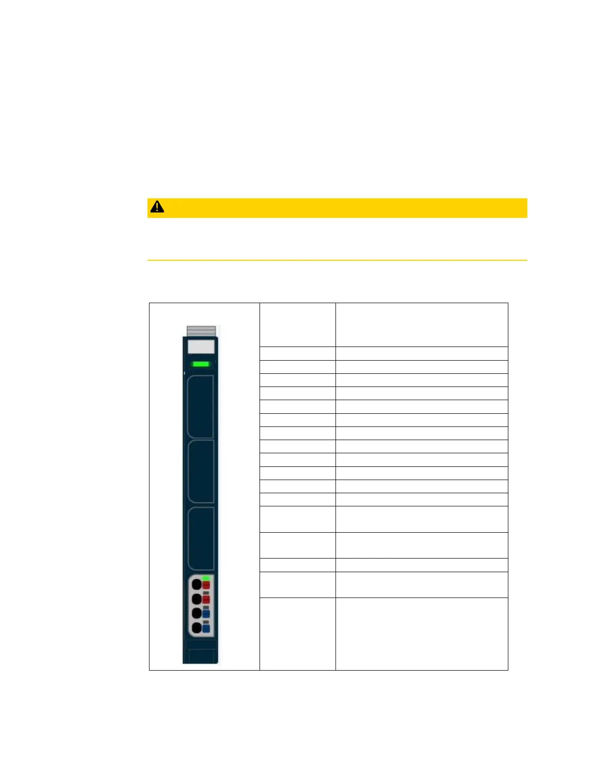
5.36.1 LED Indicators EP-7641

 Loading...


