User Manual Section 5
GFK-2958L May 2021
Detailed Description of I/O Modules 301
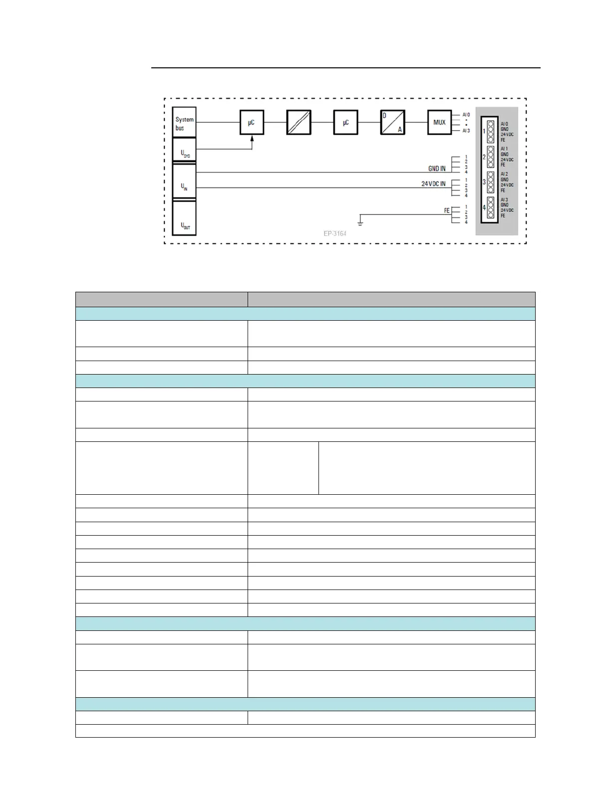
Figure 172: Block Diagram EP-3164
5.24.2 Specifications EP-3164
Process, parameter and diagnostic data depend on the network adapter
used (refer to Section, Order and Arrangement of Modules).
RSTi-EP I/O communication bus
1. Voltage (0 ... 5 V, ±5 V, 0 ... 10 V, ±10 V, 1 ... 5 V, 2 ... 10 V)
2. Current (0 ... 20 mA, 4 ... 20 mA)
0.1 % max.
50 ppm/K max.
max. –10 mV/A
at 25 °C (77 °F)
Temperature coefficient
additional inaccuracy in the voltage mode due to
sensor power supply current
max. 2 A per plug, total max. 8 A
2-wire, 3-wire, 3-wire + FE
Reverse polarity protection
Response time of the protective circuit
Individual channel diagnosis
Current consumption from system
current path ISYS,
Current consumption from input current
path IIN
25 mA + sensor supply current
For additional general data, refer to Section,

 Loading...


