EasyManua.ls Logo

Emerson PACSystems RSTi-EP - LED Indicators EP-2634

Emerson PACSystems RSTi-EP
539 pages
To Next Page IconTo Next Page
To Previous Page IconTo Previous Page
Loading...
User Manual Section 5
GFK-2958L May 2021
Detailed Description of I/O Modules 180
If you write the value 185 decimal (1011 1001 binary) in the output byte, channel 1 is set to
24 V, channel 2 is set to GND, channel 3 is deactivated and channel 4 is set to 24 V.
The module is protected against external voltages between 0 V and the operating voltage.
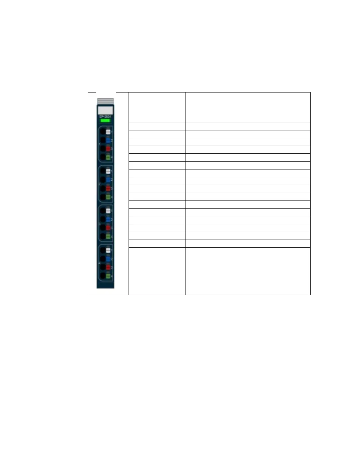
5.10.1 LED Indicators EP-2634
Module Status
Green: Communication over the system bus
Red: Module System Fault or Diagnostic Fault
1.1
Yellow: Output 0 active
1.2
--
1.3
--
1.4
--
2.1
Yellow: Output 1 active
2.2
--
2.3
--
2.4
--
3.1
Yellow: Output 2 active
3.2
--
3.3
--
3.4
--
4.1
Yellow: Output 3 active
4.2
--
4.3
--
4.4
--
For error messages refer to Section 12, LED Indicators and Troubleshooting

Table of Contents

Other manuals for Emerson PACSystems RSTi-EP

Related product manuals