User Manual Section 5
GFK-2958L May 2021
Detailed Description of I/O Modules 177
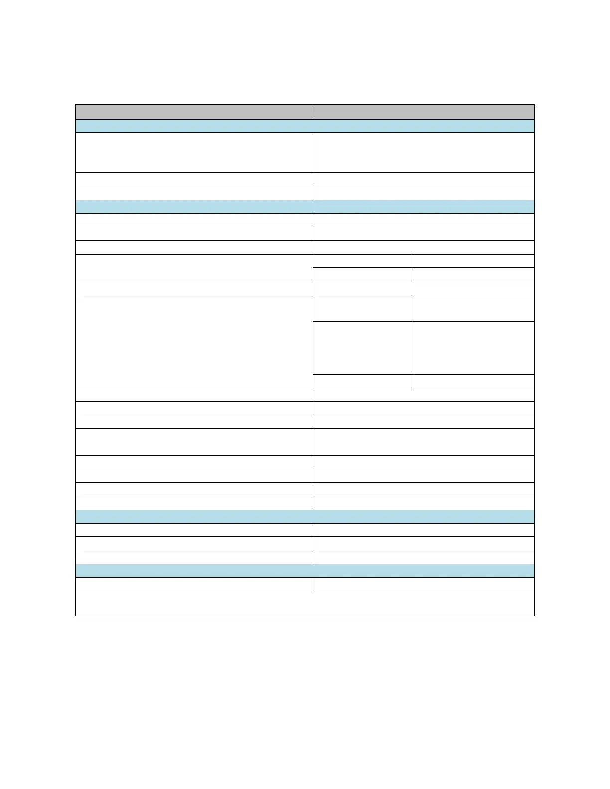
5.9.2 Specifications EP-2614
Process, parameter and diagnostic data depend on the
network adapter used (refer to Section, Order and
Arrangement of Modules).
RSTi-EP I/O communication bus
ohmic, inductive, lamp load
low » high max. 100
μ
s; high » low max. 250
μ
s
Breaking energy (inductive)
Resistive load (min.
47Ω)
0.2 Hz without free-wheeling
diode
1 kHz with suitable free-
wheeling diode
2-wire, 3-wire, 3-wire + FE
max. 2 A per plug, total max. 8 A
Constant current with thermal switch-off and
automatic restart
Response time of the current limiting circuit
Individual channel diagnosis
Current consumption from system current path ISYS
Current consumption from output current path IOUT
For additional general data, refer to Section,
General Technical Data for I/O Modules

 Loading...


