User Manual Section 5
GFK-2958L May 2021
Detailed Description of I/O Modules 153
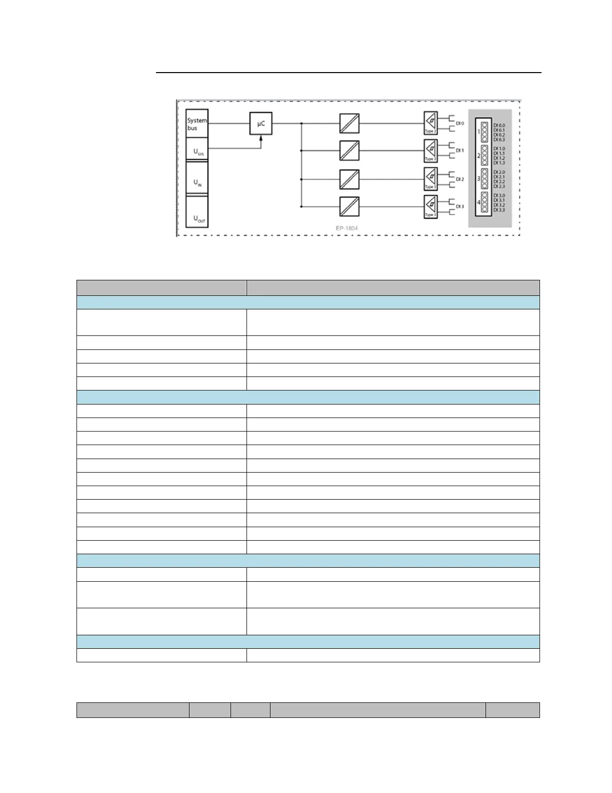
Figure 63: Block Diagram EP-1804
5.4.2 Specifications EP-1804
Process, parameter and diagnostic data depend on the network adapter
used (refer to Section 3.1, Order and Arrangement of Modules).
RSTi-EP I/O communication bus
4kV between the channels as well as between channels and power supply
400V between the channels possible
P-switching, for Type 3 sensors as per IEC 61131-2
277Vac (UL); 264,5Vac (VDE)
Individual channel diagnosis
Current consumption from system
current path ISYS
Current consumption from input current
path IIN
5.4.3 Diagnostic Data EP-1804

 Loading...


