User Manual Section 10
GFK-2958L May 2021
Replacing Components 481
the new electronic unit has been recognized and the next electronic unit is able to
be pulled out.
10.3 Replacing an I/O Module
WARNING
•
Explosion Risk - Prior to starting work, ensure that there is not a potentially
explosive atmosphere.
•
Dangerous contact voltage - Prior to removing modules, the RSTi-EP station must be
completely de-energized (supply of the field bus network adapter and all external
feed-in). Ensure that the place of installation (switch cabinet and so forth) has been
disconnected from the power supply.
CAUTION
The components in the RSTi-EP series can be destroyed by electrostatic discharge. Ensure
that personnel and work equipment are adequately earthed!
To remove an individual module from the station, all modules to the right of it and the
termination kit must be moved by approximately 5 cm (2 in).
•
To replace an I/O module
1.
Unfasten the mounting screw on the right-hand end bracket.
2.
Slide the end bracket and end plate approximately 5 cm (2 in) to the right or remove
both parts from the DIN rail.
3.
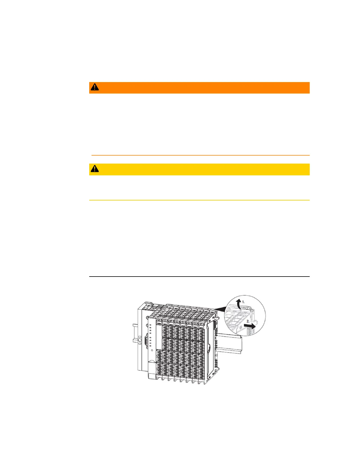
Open the release lever on the module furthest to the right.
Figure 337: Release the Lever on Rightmost Module
4.
Slide the module on the DIN rail approximately 5 cm (2 in) to the right, push it onto
the DIN rail and click the release lever into place.

 Loading...


