User Manual Section 10
GFK-2958L May 2021
Replacing Components 480
Figure 335: Use the Removal Lever to Pull the Electronic Unit Forward
4.
If the existing electronic unit was coded, insert the new coding pins into the coding
seats located in the base module.
5.
Hold the new electronic unit by the top and the bottom, and carefully slide it into
the base module.
Note: The electronic units are functionally coded so that they can only be inserted into the
appropriate base module. If it is not possible to insert a new electronic unit into the base
module, check if the combination is correct and if there is a possible mix-up.
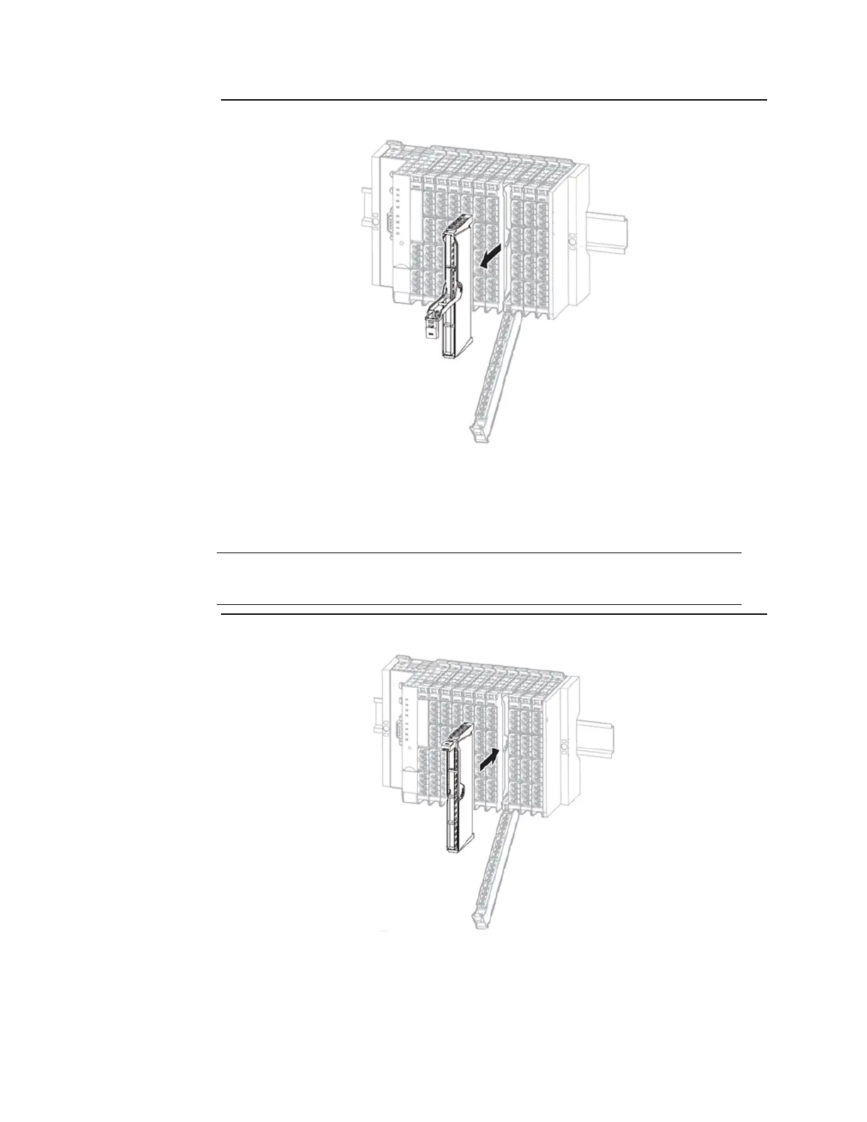
Figure 336: Slide the Electronic Unit into Position
6.
Fold the connector frame back so that it closes and clicks into place.
7.
In case of replacement during operation: Pay attention to the collective error LED
(SF) on the field-bus network adapter. Only when this doesn't light up any more,

 Loading...


