User Manual Section 5
GFK-2958L May 2021
Detailed Description of I/O Modules 374
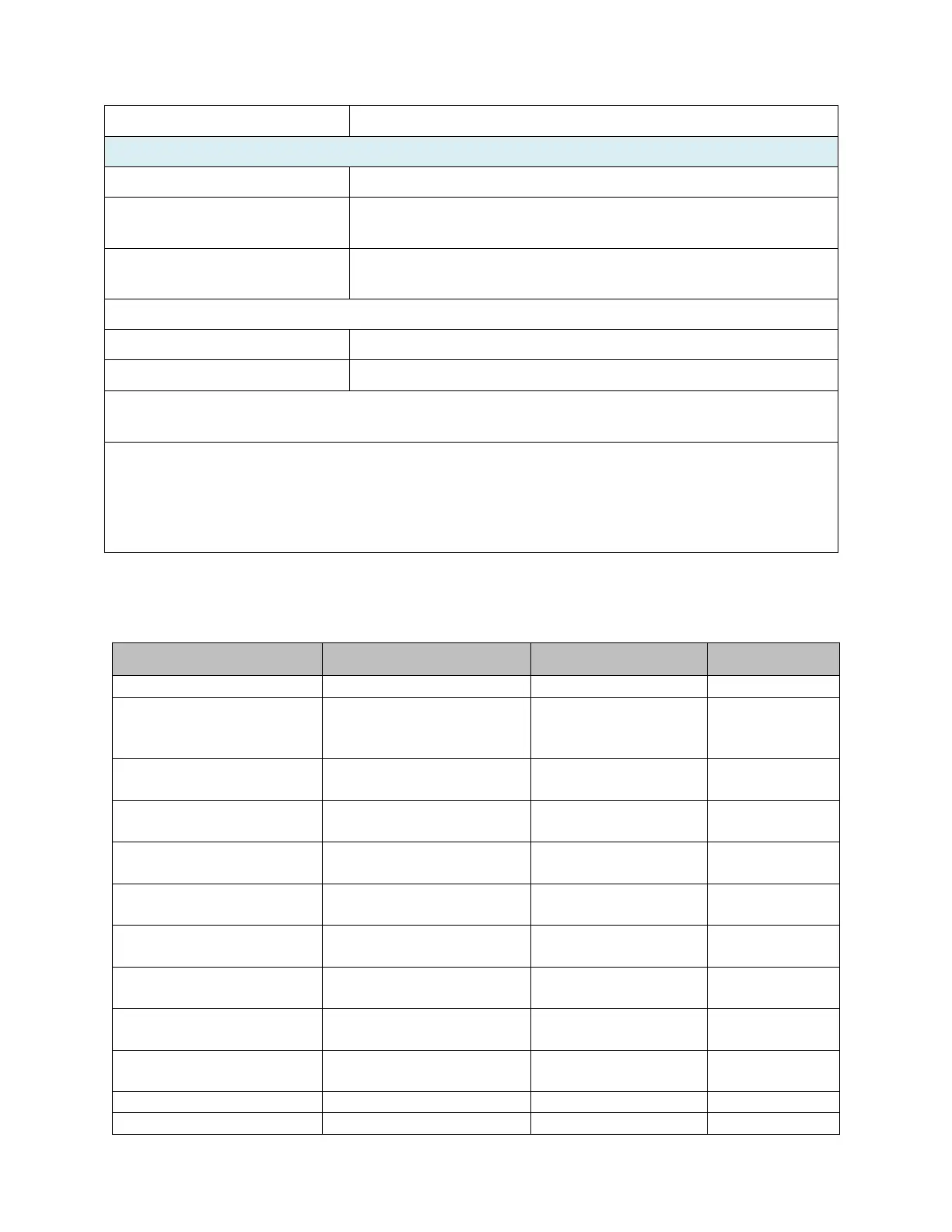
5.34.3 Modifiable Parameters for EP-1813
Selection of Harmonic, valid for
all Harmonic
measurements (min. 6 Bit)
Voltage alarm lower limit
enable
disabled (0) / enabled (1)
Voltage alarm lower limit
Positive, absolute values only
(16 Bit)
0 ... 300 V (0 ... 27648)
Voltage alarm upper limit
enable
disabled (0) / enabled (1)
Voltage alarm upper limit
Positive, absolute values only
(16 Bit)
0 ... 300 V (0 ... 27648)
Current alarm lower limit
enable
disabled (0) / enabled (1)
Current alarm lower limit
Positive, absolute values only
(16 Bit)
Current alarm upper limit
enable
disabled (0) / enabled (1)
Current alarm upper limit
Positive, absolute values only
(16 Bit)
Current imbalance alarm enable
disabled (0) / enabled (1)
Current imbalance alarm limit
4 mΩ (at 5 A), 44 mΩ (at 1 A)
Current consumption from system
current path I
SYS
Current consumption from input
current path I
IN
Weight (operational status)
For additional general data, refer to Section,
General Technical Data for I/O Modules.
1)
Nominal
input voltage with corner-grounded systems: 0 … 200 V
eff
AC.
2)
Typical frequency curve for current and voltage measurement.
3)
Current and voltage values as well as the phase angle within each phase are measured and are available with 0.5%
accuracy. All other results are based on the noted measuring values and are available with 1% accuracy.

 Loading...


