User Manual Section 7
GFK-2958L May 2021
Earthing and shielding 419
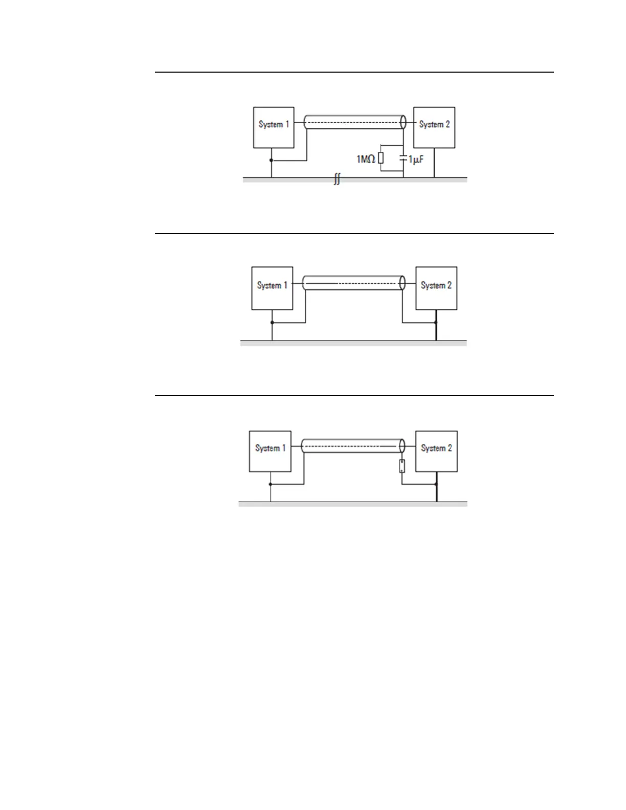
Figure 250: Shield Grounding at One End Only
If you use a two-sided shielding connection, make sure that compensating current (different
earth potentials) does not flow through the cable shield.
Figure 251: Shield Grounding at Both Ends
If you wish to avoid the disadvantages associated with creating an earth loop with two-sided
shields, it is recommended you connect one side of the shield through a high impedance.
Figure 252: Shield Grounding at Both Ends with High-Impedance at One End
For longer lengths of shielded cables, such as if a sensor must be added to a control panel, a
potential difference between both end points must not be ignored.
However, such shield conductors are relatively expensive and require more time in working
with them. Another possibility would be to place an additional voltage equalizing cable
between the measurement location and the control panel. The shield can then be hooked
up on both sides.
A high-impedance earth connection is also another option. In the control panel, the shield
is then connected to the earth potential, and the shield has a high-impedance connection
to earth at the measurement location via a gas discharge tube. This solves the problem of a
potential transfer and 50-Hz humming.
For non-isolated measurement locations, two gas discharge tubes must be installed. One
connects the shield to earth, and the other connects it to the non-isolated measurement
location. This method prevents a galvanic coupling between the measurement circuit and
the earthed measurement location.

 Loading...


