Controller 3-6
● Cherry Tampers The Cherry tamper switch located on the back wall of the cabinet
should be connected to terminals 18 and 19. The front tamper switch is also of Cherry
type and should be connected to terminals 20 and 21. The tamper switch has a cheat
feature that allows the switch to be inactive when the cabinet door is open. This is enabled
by pulling the tamper switch spigot into a forward position. Both are wired as normally
open.
● Cabinet Tamper The Class IV system has an additional cabinet tamper, which is
configured using a cabinet zone tamper. By default, zone 1 on Class IV software is assigned
as a cabinet zone tamper. The Class IV system cabinet has an inner and an outer skin,
which are wired back to zone 1. A SHORT or DISCON on this zone will generate a tamper
signal. The cabinet zone type is normally closed and terminated with a 2k2 resistor.
Cabinet tamper configuration
햽
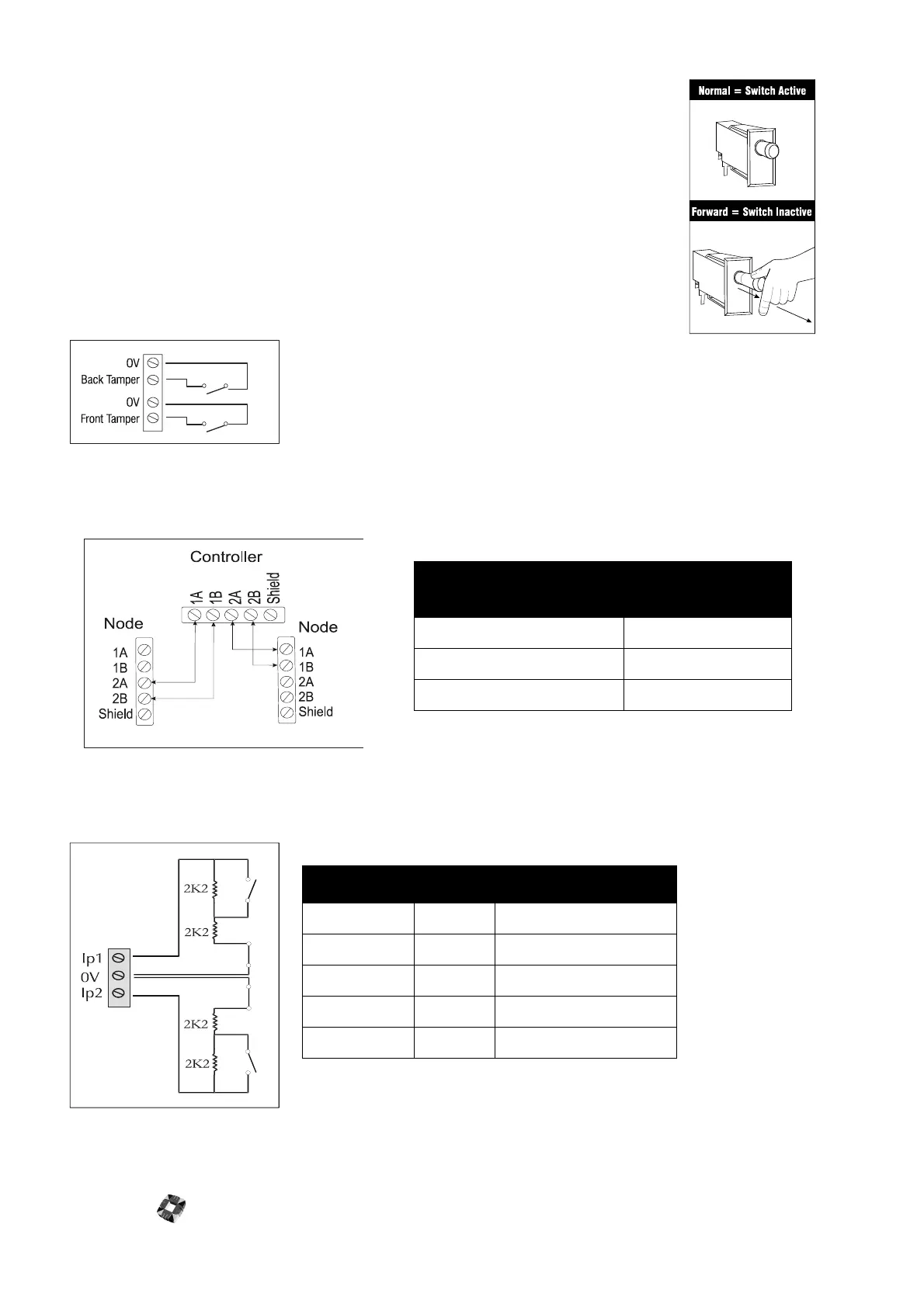
Ringnet Communications Connect the ringnet cable to the four terminals 1A to 2B. These terminals are used
for connecting the controller node onto the ringnet – see the
following connection diagram and cable type table.
햾
Inputs The Controller node has eight on-board zone inputs. These inputs are monitored using dual EOL
supervision and wired as illustrated in the following diagram and table:
햿
Earth to 0V Link.
cable type
maximum distance
between nodes
Belden 9502 500m
UTP Category: 5 solid core 1000m
Belden 9829 1000m
description value zone status
OPEN 4400 Zone open
CLOSED 2200 Zone closed
DISCON 30 000 Zone disconnected
SHORT < 1400 Zone shorted
DC SUBS Variable DC Voltage substitution