DMP 128 FlexPlus • DSP Configurator Software 28
1
Activity Panel
7
Bypass Button
2
ERL Meter
8
OK Button
3
ERLE Meter
9
Cancel Button
4
TER Meter
¢
Show/Hide Advanced Options Button
5
Reference Selection Drop-Down
£
AEC Help Button
6
Noise Cancellation Panel
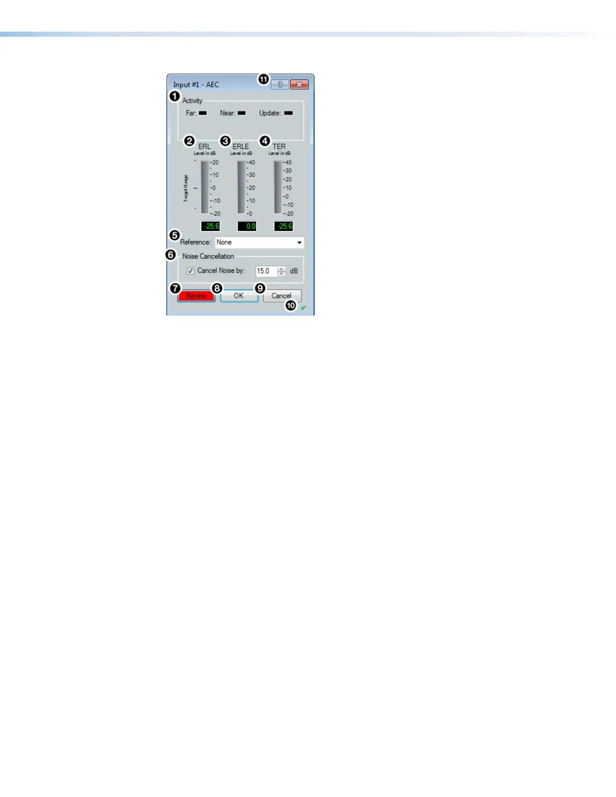
Figure 47. AEC Dialog Box
1
Activity Panel — Far lights when signal activity is detected from the far end. Near
lights when activity is detected from the near end. Update lights when AEC is updating,
converging, or reconverging.
2
ERL Meter — ERL (echo return loss) is the ratio of the far end signal at the reference
input to the far end signal received at the mic input and is expressed in dB. This meter
should read between -10 dB and +10 dB for proper AEC operation.
3
ERLE Meter — ERLE (echo return loss enhancement) is the amount of potential
echo signal that the AEC algorithm is cancelling (not including NLP processing) and is
expressed in dB.
4
TER Meter — TER (total echo reduction) is the sum of ERL and ERLE and represents
the total amount of echo reduction and is expressed in dB.
5
Reference Selection Drop-Down Menu — Provides all mic/line inputs, Aux inputs,
virtual returns, line outputs, and Expansion outputs for reference selection. When
a channel is selected as the reference, the AEC processor compares the reference
channel signal to the current input channel.
6
Noise Cancellation Panel — Provides a checkbox to engage the noise canceller
(engaged by default) and text field to enter the amount of noise reduction in dB.
7
Bypass Button — Bypasses the AEC processor. When the button is red, bypass is
enabled.
8
OK Button — Confirms changes made to the contained parameters and closes the
AEC dialog box.
figure 39. AEC Dialog Box