10.2 Basic information
10.2.1 Slots and features
external connectors
Management
VGA
Micro
SD
FRONT
USB8
PWR4
TYPE A
ROC
FAN2
SYS
P30
PC98
PWR 1
INTRUSION
DIMM1A
DIMM1B
DIMM2B
DIMM2A
Battery
JP1
JP2
TYPE C
FRONT
SMB
FRONT
USB7
ROC
SERIAL
SYS
PWR2
PANEL
Display
Port
JP3
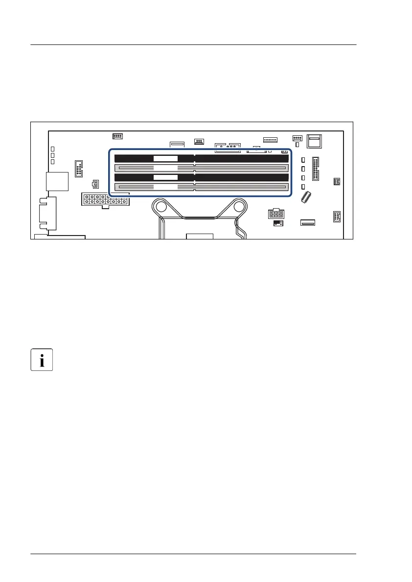
Figure 129: Memory slots overview
–
Dual DDR4 memory architecture
–
Four memory DIMM sockets
–
Up to four DDR4 UDIMMs with up to 128 GB
The notation of the CPU, memory channels and DIMM sockets correspond to
the silk print on the system board.
For system relevant information, see the hardware configurator of your
server available online at the following address:
https://www.fujitsu.com/emeia/products/computing/servers
For Japan:
https://www
.fujitsu.com/jp/products/computing/servers/primergy/
10.2.2 General memory population rules
–
Populate memory slot 1 / channel A (DIMM 1A) first.
–
Within all channels memory slot 1 must be populated prior to slot 2.
–
For maximum performance, populate both channels with the same amount
of memory (symmetric dual channel configuration).
Main memory
222 Upgrade and Maintenance Manual TX1320 M5

 Loading...