18.2 Connectors and indicators
18.2.1 Connectors and indicators on the system board
18.2.1.1
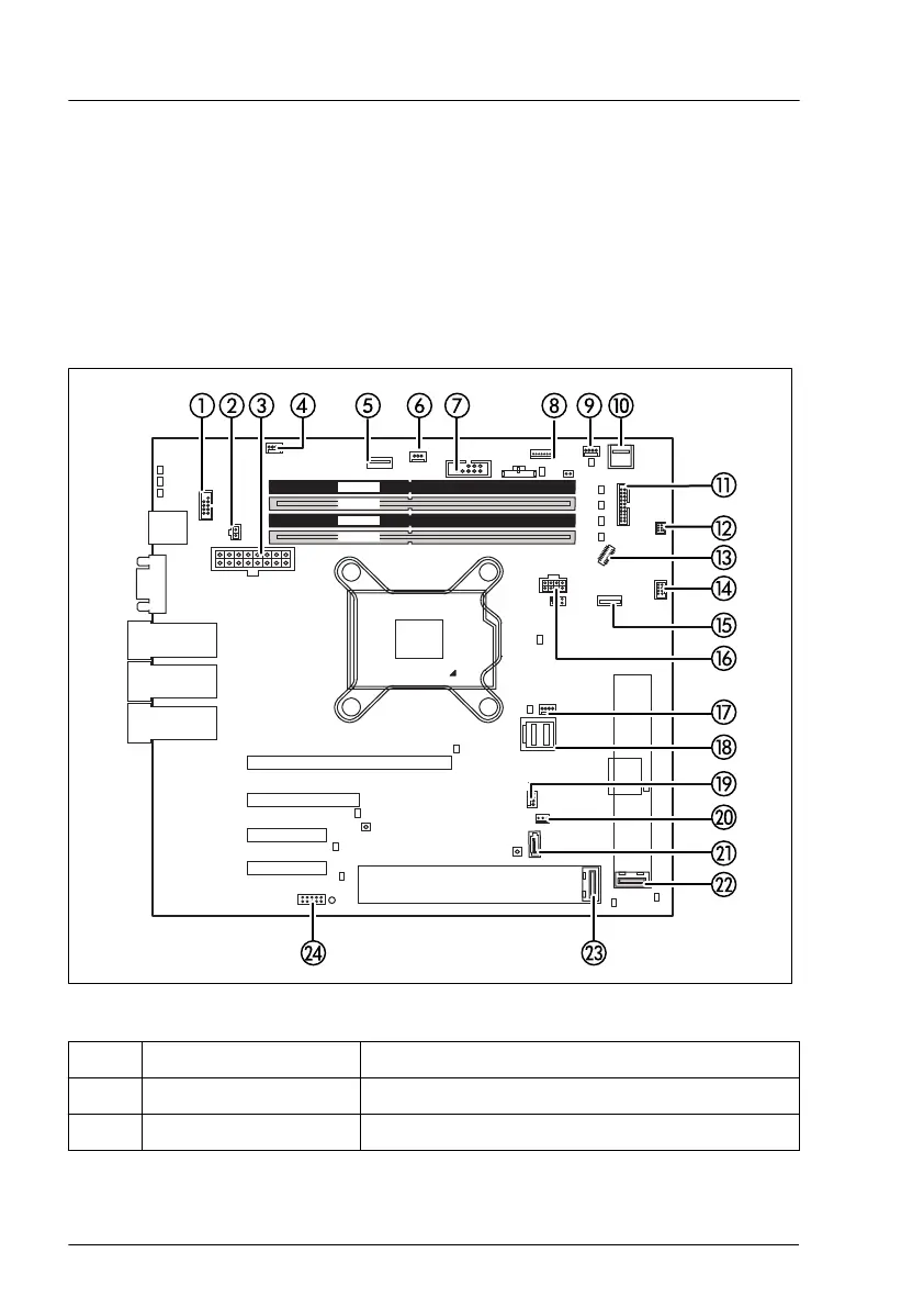
Connectors and indicators on the system board
Onboard connectors
CPU
Slot 2
Slot 1
Slot 4
Slot 3
external connectors
LAN 1
Management
LAN
LAN 2
VGA
Shared LAN 1
Micro
SD
FRONT
USB8
PWR4
TYPE A
ROC
FAN2
SYS
P30
PC98
PWR 1
iRMC
S6
TPM
INTRUSION
SATA ODD
Indicate CSS
SATA
0-3
FAN4 SYS
M.2
SSD1
DIMM1A
DIMM1B
DIMM2B
DIMM2A
Battery
HDD
LED
FAN CPU
JP1
JP2
TYPE C
FRONT
SMB
FRONT
USB7
ROC
SERIAL
SYS
Clear
RTC
PWR2
PANEL
Display
Port
JP3
M.2
SSD2
Figure 236: Internal connectors of system board D3931
No. Print Description
1 SERIAL Connector for rear wall
2 PWR2 PSU connector
Appendix A
354 Upgrade and Maintenance Manual TX1320 M5

 Loading...