18.2.3 Server rear
18.2.3.1 Connectors on the server rear
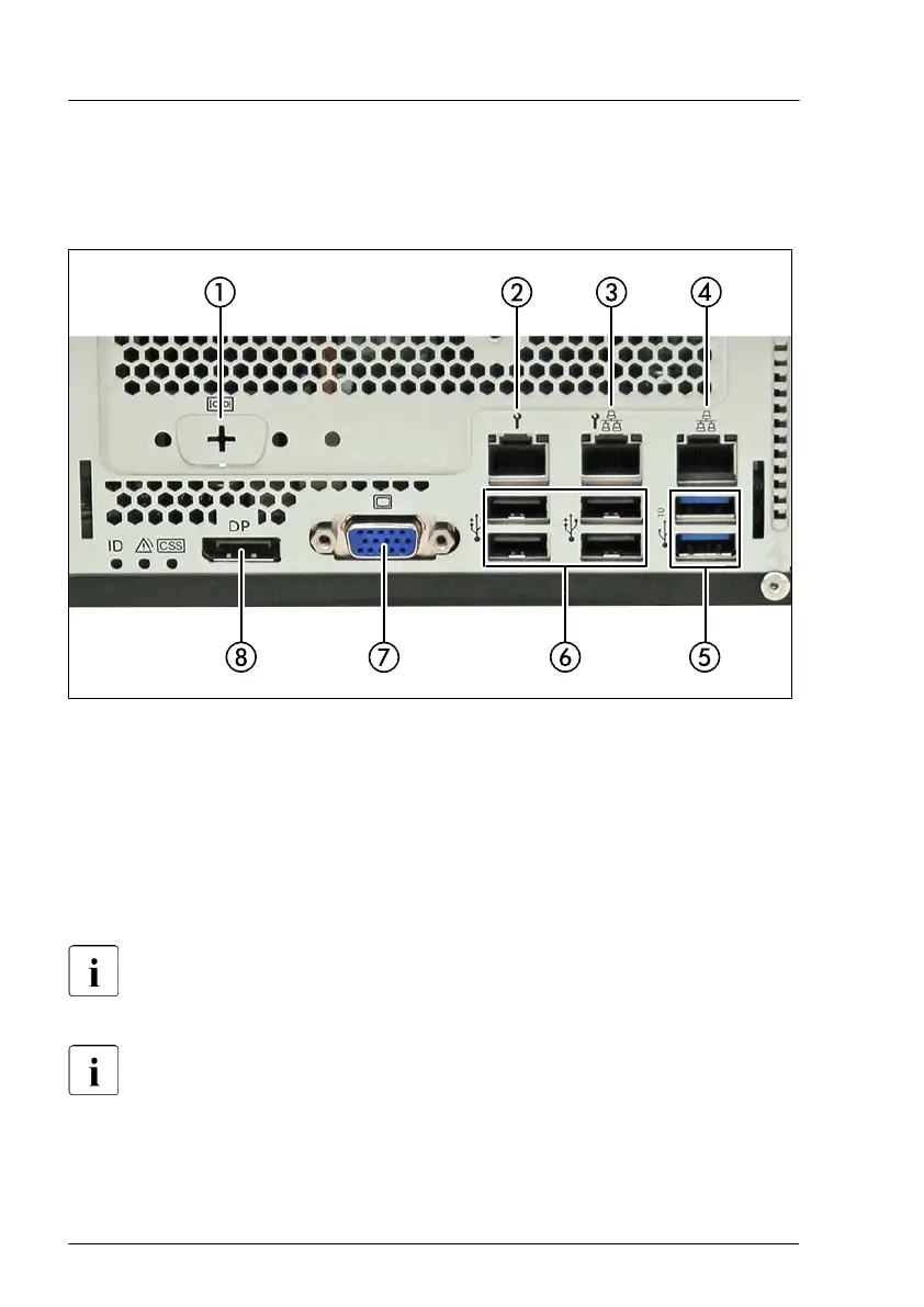
Figure 243: Connectors on the I/O panel
1
Serial interface COM1
*
2 Management LAN connector
3
Shared LAN connector (LAN1)
4 Standard LAN connector (LAN2)
5 USB 3.2 Gen 2 connectors (2x)
6 USB 2.0 connectors (4x)
7 VGA connector
8 Display Port
* The serial interface can be used as the standard interface or for
communication with iRMC.
Depending on the BIOS settings, the shared LAN connector may also
be used as a management LAN connector
. For more information, see
the corresponding BIOS Setup Utility reference manual.
Some of the devices connected require special software (e.g. drivers)
(see documentation for the connected device).
Appendix A
366 Upgrade and Maintenance Manual TX1320 M5

 Loading...