Home
Fujitsu
Server
PRIMERGY TX1330 M4
Upgrade And Maintenance Manual
Page 68 (5.5 Connecting Cables)
Fujitsu PRIMERGY TX1330 M4 - 5.5 Connecting Cables; 5.5.1 Notes on Connecting;Disconnecting Cables
565 pages
Manual
To Next Page
To Next Page
To Previous Page
To Previous Page
Loading...
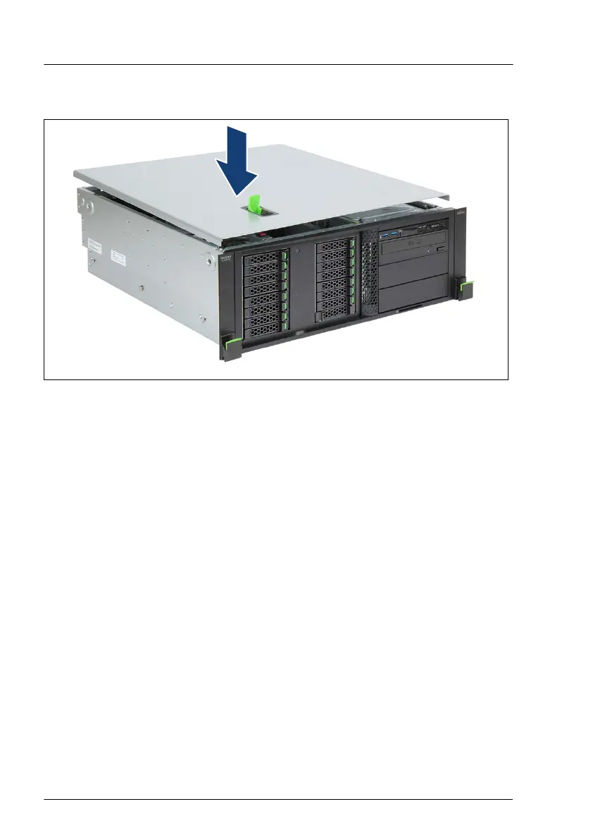
4.5.2.2
Installing the top cover
Figure 23: Installing the top cover (A)
▶
Open the locking lever on the top cover
.
▶
Lower the top cover onto the chassis, recessed by 2
cm.
Basic hardware procedures
68
Upgrade and Maintenance Manual
TX1330 M4
67
69
Table of Contents
Main Page
Section 1
7
Table of Contents
7
Notational Conventions
19
Introduction
19
Concept and Target Groups of this Manual
19
Before You Start
21
Basic Information
21
Proceeding
21
Advanced Thermal Design (ATD)
21
Installing Optional Components
22
Replacing a Defective Component
22
Customer Replaceable Units (CRU)
23
Assignment of Unit Categories
23
Classification of Procedures
23
Upgrade and Repair Units (URU)
24
Field Replaceable Units (FRU)
25
Average Task Duration
27
Tools You Need at Hand
28
Documentation Overview
28
About Availability of Manuals
28
List of Documents
28
Basic Safety Instructions
31
Important Information
31
Safety Instructions
31
Introduction
31
Before Starting up
32
Installation and Operation
32
Batteries
35
Working with Optical Disk Drives (Odds) and Media
35
Laser Information
37
Modules with Electrostatic-Sensitive Devices (ESD Modules)
37
Transporting the Server
39
Installing the Server in the Rack
40
Other Important Information
40
Energy Star
41
CE Conformity
41
FCC Class a Compliance Statement
42
Environmental Protection
43
Basic Hardware Procedures
45
Using Diagnostic Information
45
Proceeding
45
Locating the Defective Server
45
Determining the Error Class
46
Locating the Defective Component
46
Shutting down the Server
47
Disconnecting the Power Cord
48
Disconnecting the Power Cord (Standard PSU)
48
Disconnecting the Power Cord (Hot-Plug PSU)
49
Getting Access to the Component
50
Safety Notes
50
Rack Model
50
Extending the Server out of the Rack
50
Removing the Server from the Rack
51
Removing the Top Cover
54
Removing the Rack Front Cover
55
Floorstand Model
58
Unlocking the Server
58
Removing the Side Cover
60
Removing the Accessible Drive Bay Cover
61
Removing the HDD Bay Cover
63
Removing the Front Cover
63
Installing the Rack Front Cover
66
Rack Model
66
Safety Notes
66
Reassembling
66
Installing the Top Cover
68
Installing the Server in the Rack
69
Sliding the Server into the Rack
72
Floorstand Model
73
Installing the Front Cover
73
Installing the HDD Bay Cover
75
Installing the Accessible Drive Bay Cover
76
Installing the Side Cover
77
Locking the Server
78
Connecting the Power Cord
79
Connecting the Power Cord (Standard PSU)
79
Connecting the Power Cord (Hot-Plug PSU)
80
Switching on the Server
81
Handling the System Fan Module
82
Removing the System Fan Module
82
Installing the System Fan Module
85
Handling Accessible Drive Bays
89
Opening the Accessible Drive Locking Bar
89
Closing the Accessible Drive Locking Bar
91
Removing Accessible Drive Filler Covers
92
Accessible Drive Filler Covers
92
Installing Accessible Drive Filler Covers
93
Accessible Drive Covers
95
Removing Accessible Drive Covers
95
Installing Accessible Drive Covers
96
Handling the Anti-Tilt Bracket
97
Installing the Anti-Tilt Bracket
97
Removing the Anti-Tilt Bracket
98
Suspending Bitlocker Functionality
99
Starting the Maintenance Task
99
Validation
99
Basic Software Procedures
99
Disabling the Boot Watchdog
100
Removing Backup and Optical Disk Media
102
Verifying and Configuring the Backup Software Solution
102
Switching on the ID Indicator
102
Completing the Maintenance Task
103
Updating or Recovering the BIOS and Irmc S5
103
Verifying System Information Backup or Restore
105
Updating Expansion Card Firmware
106
Enabling Option ROM Scan
107
Reconfiguring the Backup Software Solution
108
Resetting the Boot Retry Counter
108
Resetting the Error Status after Replacing Memory Modules or Cpus
110
Resetting the Error Status after Replacing Memory Modules
110
Resetting the Error Status after Replacing Cpus
112
Enabling the Boot Watchdog
114
Enabling Replaced Components in the BIOS
115
Verifying the Memory Mode
116
Verifying the System Time Settings
116
Viewing and Clearing the System Event Log (SEL)
117
Updating the NIC Configuration File in a Linux and Vmware Environment
120
Resuming Bitlocker Functionality
121
Performing a RAID Array Rebuild
122
Looking for MAC/WWN/GUID and SAS Addresses
123
Basic Information
123
Looking for the MAC Address of a LAN Controller
123
Looking for the WWN Address of a Fibre Channel Controller
124
Looking for the GUID Address of an Infiniband or Omni-Path Controller
125
Looking for SAS Addresses of SAS Controllers for External Devices
125
Using the Chassis ID Prom Tool
126
Configuring LAN Teaming
128
Switching off the ID Indicator
129
Performing a Fan Test
130
Specifying the Chassis Model
131
Power Supply Unit (PSU)
133
Safety Notes
133
Basic Information
133
Standard Power Supply
135
Replacing the Standard PSU
135
Redundant Power Supply
145
Installing a Hot-Plug PSU
145
Removing a Hot-Plug PSU
148
Replacing a Hot-Plug PSU
152
Replacing the Power Distribution Board
154
Fujitsu Battery Unit (FJBU)
159
Installing an FJBU
159
Removing an FJBU
161
Replacing an FJBU
163
Converting a Standard Power Supply to a Redundant Power Supply
164
Hard Disk Drive (HDD) / Solid State Disk (SSD)
169
Safety Notes
169
Basic Information
170
Handling Hdds or Ssds Without Installation Frame
175
Inch HDD/SSD and 2.5-Inch Installation Frame
175
Inch HDD/SSD and 3.5-Inch Installation Frame
177
Inch HDD and 3.5-Inch Installation Frame
178
Inch HDD Configurations
181
Equipping the 3.5-Inch HDD Bays
181
Overview of Configurations
181
Configuration with up to Four HDD Modules
181
Configuration with up to Eight HDD Modules
182
Configuration with up to 12 HDD Modules
183
Configuration with Additional Pcie SSD Modules
184
Installing 3.5-Inch HDD Modules
185
Removing 3.5-Inch HDD Modules
188
Replacing a 3.5-Inch HDD Module
190
Replacing a 3.5-Inch HDD Backplane
192
Upgrading Configuration from up to Four to up to Eight 3.5-Inch Hdds
203
Inch HDD/SSD Configurations
209
Overview of Configurations
209
Configurations with up to Eight HDD/SSD Modules
209
Configurations with up to 16 HDD/SSD Modules
210
Configurations with up to 24 HDD/SSD Modules
211
Configurations with Additional Pcie SSD Modules
213
Installing 2.5-Inch HDD/SSD Modules
214
Removing 2.5-Inch HDD/SSD Modules
216
Replacing a 2.5-Inch HDD/SSD Module
219
Replacing a 2.5-Inch HDD Backplane
221
Upgrading Configuration from Eight to 16 2.5-Inch Hdds/Ssds
236
HDD Extension Box
241
Installing the 8X 2.5-Inch HDD/SSD Extension Box
241
Removing the 8X 2.5-Inch HDD/SSD Extension Box
247
Replacing the HDD/SSD Backplane or Pcie SSD on the 8X
250
Inch HDD/SSD Extension Box
250
Installing the 4X 3.5-Inch HDD Extension Box
256
Removing the 4X 3.5-Inch HDD Extension Box
260
Replacing the HDD Backplane on the 4X 3.5-Inch HDD Extension Box
262
SAS Expander Board
268
Installing the SAS Expander Board
268
Removing the SAS Expander Board
273
Replacing the SAS Expander Board
275
Fans
277
Safety Notes
277
Basic Information
277
Replacing the System Fan
279
Expansion Cards and Backup Units
287
Safety Notes
287
Basic Information
287
Handling Slot Brackets
289
Installing Slot Brackets
289
Removing Slot Brackets
290
Handling SFP+ Transceiver Modules
291
Installing SFP+ Transceiver Modules
291
Removing SFP+ Transceiver Modules
296
Installing an Expansion Card
299
Expansion Cards and Riser Cards
299
Removing an Expansion Card
305
Replacing an Expansion Card
308
Replacing a Riser Card
310
Replacing a TFM
313
Flash Backup Unit (FBU)
318
Positions of the Fbus
318
Installing an FBU
319
Removing an FBU
324
Replacing an FBU
328
Main Memory
331
Safety Notes
331
Basic Information
332
Slots and Features
332
General Memory Population Rules
332
Modes of Operation
333
Installing Memory Modules
333
Removing Memory Modules
336
Replacing Memory Modules
338
Basic Information
341
Safety Notes
341
Processor (CPU)
341
Upgrading or Replacing the CPU
342
Replacing the Heat Sink
353
Handling the Protectice Cover
355
Accessible Drives
361
Safety Notes
361
Basic Information
361
Installing Accessible Drives
364
Removing Accessible Drives
370
Replacing Accessible Drives
372
Slimline ODD in Multibay Box
373
Installing the Slimline ODD
373
Removing the Slimline ODD
378
Replacing the Slimline ODD
383
Ultraslim ODD in 3.5-Inch HDD Extension Box
384
Installing the Ultraslim ODD
384
Removing the Ultraslim ODD
390
Replacing the Ultraslim ODD
393
Ultraslim ODD in an Ultraslim ODD Adapter
394
Installing the Ultraslim ODD
394
Removing the Ultraslim ODD
398
Replacing the Ultraslim ODD
400
Front Panel
403
Safety Notes
403
Replacing the Front Panel Module
403
System Board and Components
413
Safety Notes
413
Basic Information
413
CMOS Battery
414
Replacing the CMOS Battery
414
Installing the TPM
417
TPM Kit
417
Trusted Platform Module (TPM)
417
Removing the TPM
421
Replacing the TPM
425
Irmc Microsd Card
427
Note for Embedded Lifecycle Management (Elcm)
427
Installing the Irmc Microsd Card
427
Removing the Irmc Microsd Card
429
Replacing the Irmc Microsd Card
431
Slots and Bolts for M.2 Ssds
432
M.2 Ssd
432
Installing an M.2 SSD
433
Removing an M.2 SSD
437
Replacing an M.2 SSD
439
Dual Microsd 64GB Enterprise
440
Position of the Dual Microsd 64GB Enterprise
440
Installing the Dual Microsd 64GB Enterprise
441
Removing the Dual Microsd 64GB Enterprise
443
Replacing the Dual Microsd 64GB Enterprise
445
Replacing the Microsd Card
447
Replacing the System Board
449
System Board
449
Converting a Floorstand Model to a Rack Model
459
Cabling
475
Replacing the Intrusion Switch Cable
475
Mechanical Overview
487
Server Front
487
Inch HDD/SSD Model
487
3.5-Inch HDD Model
488
Server Rear
490
Server Rear with Standard PSU
490
Server Rear with Hot-Plug Psus
491
Server Interior
492
Server with Standard PSU
492
Server with Hot-Plug Psus
493
Connectors and Indicators
494
Connectors and Indicators on the System Board
494
Server Front
499
Connectors on the Front Panel
499
Indicators on the Front Panel
500
Indicator on the ODD
503
Indicators on the Hot-Plug HDD/SSD Module
504
Server Rear
506
Connectors on the Server Rear
506
ID, CSS and Global Error Indicators
507
LAN Indicators
509
Indicator on Hot-Plug PSU
511
Indicator on FJBU
512
Acoustic Indicators
513
Onboard Settings
515
Minimum Startup Configuration
516
Supplied Documents
519
Section 2
521
Basiccabling3Bpl
522
List of Used Cables
522
Oobcabling2Bpl_With_Nvme
522
Oobcabling3Bpl_With_Nvme
527
Powercablingstdpsu
528
Powercablingredpsu2Bpl
529
Powercablingredpsu3Bpl
530
Powercablingredpsu2Bplwithnvme
531
Powercablingredpsu3Bplwithnvme
532
Sata_1X4_3.5
533
Sata_1X4_2.5
534
Sas_1X4_3.5_Cpep4X0I
535
Sas_1X4_3.5_Cp2100-8I
536
Sas_1X4_3.5_Ep5X0I
537
Sas_2X4_3.5_Cpep4X0I
538
Sas_2X4_3.5_Cp2100-8I
539
Sas_2X4_3.5_Ep5X0I
540
Sas_Cpep4X0I_Exp
541
SAS_CP2100-8I_Exp
542
Sas_Ep5X0I_Exp
543
Sas_Exp_3X4_3.5
544
Sas_1X8_2.5_Cpep4X0I
545
Sas_1X8_2.5_Cp2100-8I
546
Sas_1X8_2.5_Ep5X0I
547
Sas_Exp_2X8_2.5
548
Sas_Exp_3X8_2.5
549
Ep5X0I_Nvme_Extensionbox
550
Accdrv_Lto_Riserpci32
551
Option Riserslot
552
Accdrv_Lto_Rdx
553
Dual_Micro_Sd_64Gb_Enterprise
554
System Fans Standard
555
System Fans Redundant
556
Other manuals for Fujitsu PRIMERGY TX1330 M4
Operating Manual
110 pages
Related product manuals
Fujitsu PRIMERGY TX1330 M2
86 pages
Fujitsu PRIMERGY TX1330 M3
92 pages
Fujitsu PRIMERGY TX1330 M1
86 pages
Server PRIMERGY TX1330 M1
336 pages
Fujitsu PRIMERGY TX1320 M4
102 pages
Fujitsu PRIMERGY TX2550 M4
88 pages
Fujitsu PRIMERGY RX2530 M4
88 pages
Fujitsu PRIMERGY RX2540 M4
86 pages
Fujitsu PRIMERGY CX2560 M4
70 pages
Fujitsu PRIMERGY CX2550 M4
70 pages
Fujitsu PRIMERGY RX1330 M4
106 pages
PRIMERGY CX25 0 M4 Series
76 pages

 Loading...