GE MEDICAL SYSTEMS PROPRIETARY TO GE
D
IRECTION 2294854-100, REVISION 3 LOGIQ™ 9 PROPRIETARY MANUAL
8-22 Section 8-4 - Back End Processor Power Supply Replacement
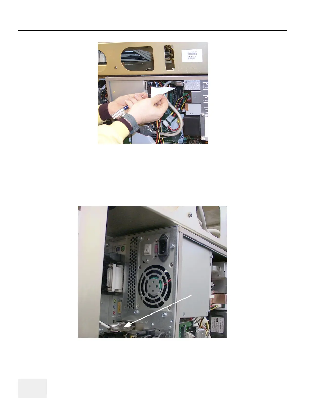
9.) Refer to Figure 8-15 on page 8-22 . Remove the UPS Control cable (C12) from the back of the BEP.
10.)After the UPS Control cable is removed, loosen the screws of the UPS Control connector at the PCI
slot panel. This should allow you to detach the connector from the back of the BEP and push it into
the BEP case. This cable/connector assembly is part of the BEP Power Supply and must be
removed with the supply.
11.)Support the power supply while removing the 4 screws from the back of the power supply, as shown
in Figure 8-16 on page 8-23
Figure 8-14 Remove Angle Bracket
Figure 8-15 C12 UPS Connector