Notes:
•
Since this trim function “from Motor” is ef-
fective only in direction, the display of your
transmitter will change accordingly if the
encoder direction to the collective pitch minimum
position of the C1 stick from “back” - whereupon
the above gures change on “front “menu” heli-
copter type in the line ”pitch min“ . Also replace
the effects shown the page, if you pitch left in the
line change of Pitc right ”control assignment“ of
the menu Basic setting model”.
• Take advantage of the »Servo display« to ob-
serve the inuence of the throttle limit control. The
»Servo display« screen can be reached from al-
most any menu position with a simultaneous tap
on the selection keys of the left four-way but-
ton, Bear in mind that servo output 6 controls the
throttle servo on the transmitters
mc-16 HoTT
and mc-20 HoTT!
• A servo connected to output 8 or 12 can be used,
independently of this, for other purposes by
means of mixers, provided that this servo is de-
coupled from the operating element specied by
input function “Lim.” via the »Mix only channel«
menu; see page 212.
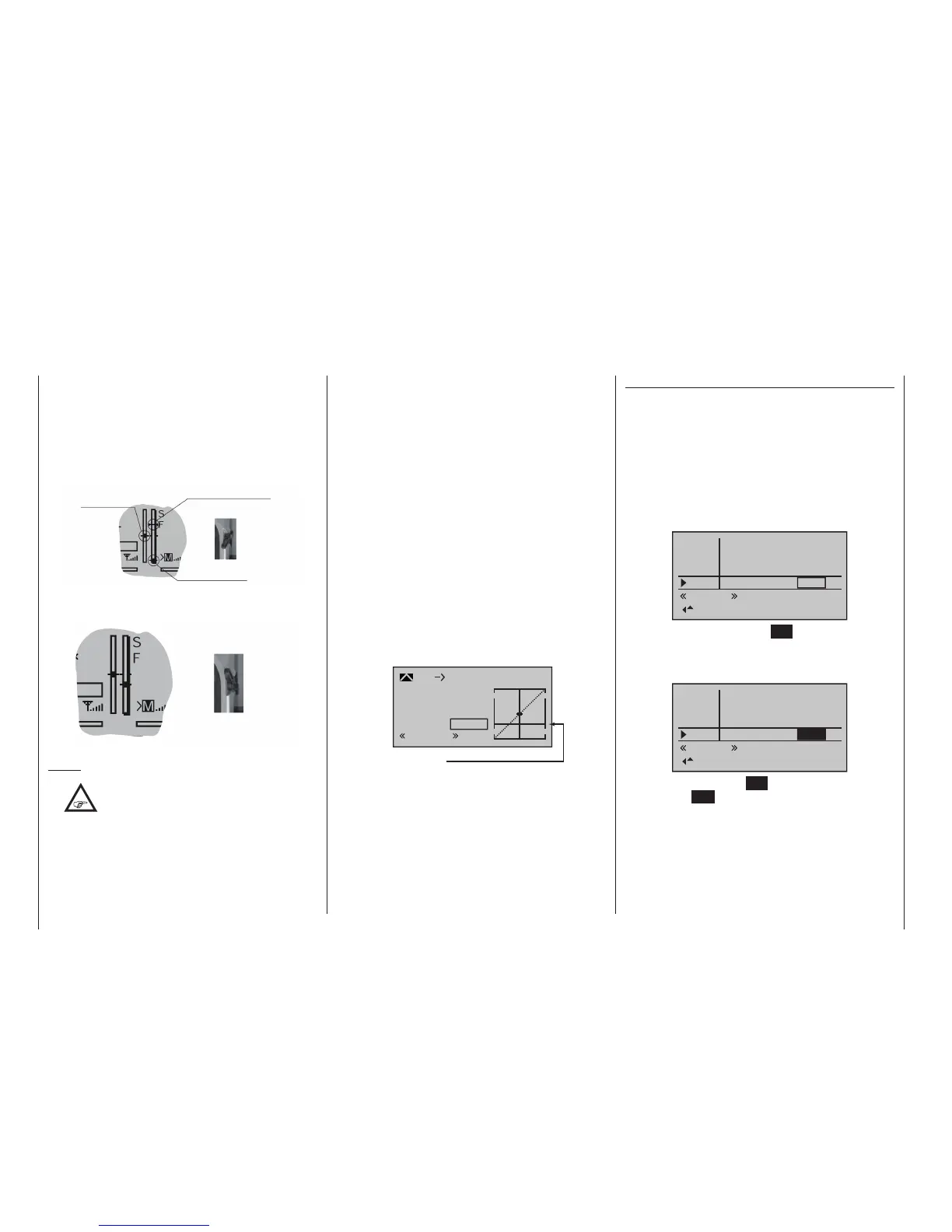
• The throttle restriction set by the throttle limiter is
shown as a horizontal bar in the throttle curve di-
agram on the second display page of the “C1
Throttle” option in the »Helicopter mixer« menu
(see page 188). The output signal for the throt-
tle servo cannot be higher than the level set by the
horizontal bar:
2
+50%
+50%
+50%
normal
Throttle limiter position
Input
Output
Point
C1 Thro
Curve
off
The above diagram shows precisely this scena-
rio: in the above example, the throttle limit control
is set to about +20 % and thus restricts the move-
ment of the throttle servo to about +20 % of full
travel.
Time delay for the throttle limiter
To safely prevent the carburettor from opening too rap-
idly, assign the throttle limiter input “Lim.” to a time de-
lay that takes effect only in the direction of full throttle.
This applies especially if the throttle limiter is controlled
by a switch rather than, as preset, with the right-side
proportional rotary slider.
To set a delay time, push the throttle limit control to
its forward limit or move the switch into its full-throttle
position then use the selection keys of the left or right
four-way button to select the “– time +” column:
In5
– time +
0.0s
0.0s
0.0s
0.0s
Thro
Gyro
Lim.
0.0s
0.0s
0.0s
0.0s
normal
After a brief tap on the centre SET key of the right
four-way button, the selection keys of the left or right
four-way button can be used to select the desired time
delay, e. g. 5 seconds:
In5
– time +
0.0s
0.0s
0.0s
Thro
Gyro
Lim.
0.0s
0.0s
0.0s
0.0s
normal
5.0s
A brief tap on the centre SET key of the right four-way
button or the ESC key of the left four-way button will
complete the entry.

 Loading...


