148
Program description - Phase settings | Winged models
Phase settings
Setting up flight phases
Setting up ight phases
When you set up flight phases for fixed-wing aircraft
models, you start with this menu. You assign individual
phases a name and also assign a period of time for a
(soft) transition into each phase. Note that – depending
on your model and your settings – switch times much
longer than the default 0.1 s have proven useful. You
can also set up several phases with names and transi-
tion times even if you don’t currently have a use for
them, since the decision as to which of the “occupied”
phases you activate is made only on the »Phase as-
signment« menu, page 154, when setting “phase
switches”.
Whether or not one of the phases 1 … 7 currently has
an assigned switch and the state of the switch can be
seen in the “status” column second from left:
Symbol Meaning
– No switch assigned
+ Phase can be accessed via switch
Indicates the phase currently active
“Name” column
Briefly tap on the centre SET key of the right four-way
button then assign the needed phases (phase 1 up to
maximum of 7 phases) by picking their names from the
selection list with the selection keys of the left or right
four-way button.
The order in which phases 1 to max. 7 are assigned is
entirely irrelevant and you can leave gaps as you wish.
Nonetheless, you should always start with “Phase 1”,
the “Normal phase”, which is always active if …
• … no phase switch is set in the »Phase assign-
ment« menu or if
• no phase has been assigned to specific combina-
tions of switches.
This option is available on both transmit-
ter types.
Within one model memory, the transmit-
ters
mc-16 HoTT and mc-20 HoTT
lets you program up to 7 discrete groups of settings for
various conditions met during the flight. The grouped
settings are typically termed “flight phases” and are
programmed in the corresponding menus.
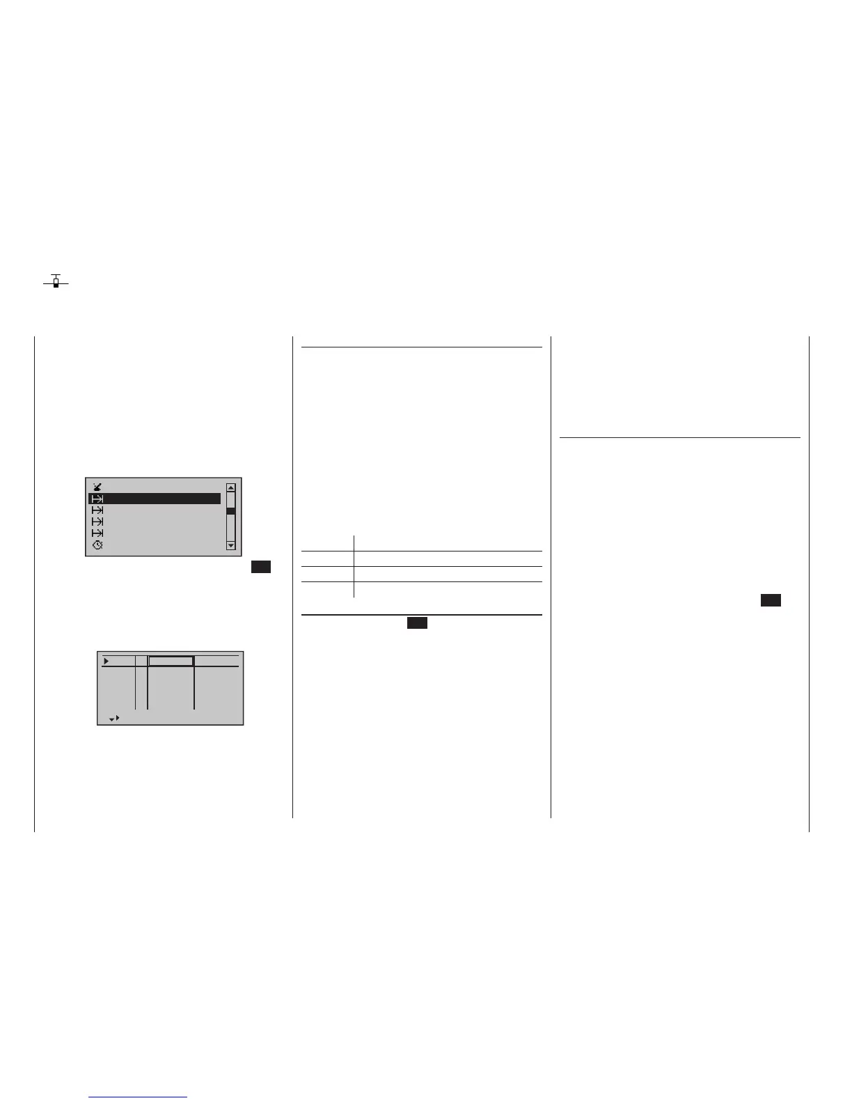
Use the selection keys of the left or right four-way but-
ton to scroll to the »Phase settings« menu option in
the Multi-function menu:
Phase settings
Phase assignment
Phase trim
Logical switch
Timers (general)
Non-delayed chan
Open this menu option with a tap on the centre SET
key of the right four-way button.
Depending on the setting in the “Motor at Ch1” line of
the »Model type« menu (page 98), your transmitter’s
screen will offer you the additional columns “Motor”
and “Sw.time” (transition time) or just the column “Sw.
time” (transition time) for your settings to the…
Pha1
Pha2
Pha3
Name ph.Tim.
Pha4
Pha5
normal
Start
Strecke
–
–
–
–
... right of the “ph. Tim” (flight phase timers) when you
call up the »Phase settings« menu point
The definition of the phase name “Normal” could there-
fore be a useful one to adopt for “Phase 1”. The names
themselves have absolutely no technical significance
for programming; their only purpose is to help you to
identify which phase is active at any time and are thus
displayed in all flight phase-dependent menus and also
on the transmitter’s basic display.
Column “ph.Tim.”
In addition to the standard timers on the basic screen
display, other timers are also available whose settings
are configured in the »Flight phase timers« menu,
page 162.
Clk 1, Clk 2, Clk 3, Lap, Time1, Time2
The flight phase timers “Clk 1 … 3” plus “Time1” and
“Time2” run only in the flight phase to which they have
been assigned in this menu. During other flight phases
they are stopped (and hidden) and the assigned stop/
start switch then has no effect.
The lap counter, once started, continues to run
through changes of phase, however, although it can be
stopped during any flight phase via the centre ESC key
of the left four-way button.
While you can obviously record lap times using “Lap”
and a switch, the two timers “Time1” and “Time2” have
the following meaning:
• Time1
This timer will only measure time during which the
switch or control switch assigned in the “Lap time/
Tim tab” line of the »Flight phase timers« menu,
page 162, is “closed”. The frequency at which
the switch is activated is shown on the basic dis-
play. This counter field is highlighted as soon as the
switch for the “Time1” timer is “opened”, i. e. the
timer is stopped:
mc
16 20

 Loading...


