149
Program description - Phase settings | Winged models
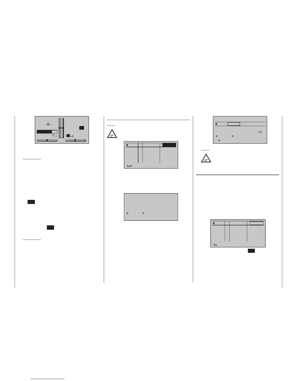
GRAUBELE
#01
2:22h
Stp
Flt
«Speed »
K78
0:00
0:00
5.5V
3.9V
0:00.0
M
Time1
00
When necessary, the selection keys can be used to
access and read the sequence of switching times.
Application:
Measurement of e. g. motor switch-on times, if the
same switch also actuates the motor.
• Time2
This timer stores both the “off” and the “on” periods
for the associated switch, i. e. every switch actua-
tion in either direction will cause a record to be writ-
ten for the timer, the timer will be reset then starts
incrementing by “1” again as time passes.
Each time count can be suspended with the cen-
tre ESC key of the right four-way button, without
actuating the switch itself. Activating the switch, in
turn, increments the counter by 1 and restarts the
“Time2” timer.
In order to read out the time memory with the selec-
tion keys, the “Time2” timer must first be suspend-
ed by using the ESC key of the right four-way but-
ton.
Application:
In addition to the motor runtimes, for example, the
unpowered glide times between these could also
be recorded.
A simultaneous tap on the or keys of the right
four-way button (CLEAR) will reset suspended timers
shown in the basic display.
Column “Motor”
Note:
This column is only available if “forward/back”
is present in the “Motor on C1” line of the
»Model type« menu.
Pha1
Pha2
Pha3
Name motor
Pha4
Pha5
+
+
Normal
Launch
Dist.
–
–
yes
yes
yes
yes
yes
• “yes”
The motor connected to receiver output 1 will be
controlled by the C1 stick (throttle/brake stick).
The brake system to be set up on the »Wing mix-
ers« menu is deactivated:
Brake settings
normal
normal
OFF
• “no”
The motor connected to receiver output 1 is decou-
pled from the C1 stick (throttle/brake stick) and is
held in its OFF position – as specified by the setting
“Throttle min. forward / back” – automatically.
The brake system to be set up in the »Wing mix-
ers« menu is activated and is actuated by the C1
stick:
Elevat curve
Brake settings
AILE
Crow
D.red
0%
0%
0%
0%
0%
0%
WK WK2
normal
Note:
The settings available depend on the
number of control surface servos selected
on the line “Ailerons/Camber-changing
aps in the »Model type« menu.
Column “Sw. time”
When you switch between flight phases, it is advisable
to use this column to program a switch time for a “soft”
transition INTO (!) the respective phase. Accordingly,
there is also an option for specifying a different time for
the switchover from any phase to, for example, Phase
3 than for a switchover to Phase 1.
Use the selection key of the left or right four-way
button to move the marker frame to the right beyond
the column labelled “Timer” and, if applicable, also the
column labelled “Motor”.
Pha1
Pha2
Pha3
Name Sw.time
Pha4
Pha5
+
+
Normal
Launch
Dist.
–
–
0.1s
0.1s
0.1s
0.1s
0.1s
Following a brief tap on the centre SET key of the right
four-way button, the switchover time value in the field
displayed in inverse video can be changed within a
range of 0 and 9.9 s:

 Loading...


