179
Program description - Wing mixers
Note:
The values shown in the line “Fl.pos” access to
the same record about how to comparable
point in the column “AI”, “AI2”, “FL”
and possibly “FL2” menu “phase trim” (page
156) displayed, which is why changes always have a
direct effect mutually.
FL (Effect of flap control)
This line specifies the percentage of effect produced
on aileron and flaps by the settings (if applicable, also
flight-phase dependent settings) made for Input 6 in
the »Control adjust« menu, page 112.
0%
0%
0%
AILE
0%
+100%
FL
fl.pos
normal
Diff.
Ail-tr
0%
+100%
+100%
FLAP
0%
0%
FL
fl.pos
normal
Diff.
Ail-tr
For each flap pair, you can define either a symmetrical
or an asymmetric effect. Position the transmitter control
accordingly – either centrally or to the relevant side.
If each travel adjustment is left at +100 % on the »Con-
trol adjust« menu, page 112, then values between
5 % and 20 % should generally be sufficient here.
A simultaneous tap on the or keys of the right
four-way button (CLEAR) will reset the given active
(inverse video) field to its default value shown in the
figures.
Note:
•
By default, NO transmitter control is as-
signed to input 6 on the »Control adjust«
menu. However, you can assign a trans-
mitter control or switch to this input at any
time – also in a ight phase-dependent way – thus
enabling different ap settings within a ight
phase; see also example 2 on page 304.
• As already mentioned in the remarks in the sec-
tion starting on page 166, the two INC/DEC but-
tons (CTL 5 or 6) are virtually ideal for this pur-
pose, as their position is automatically stored.
They are tted as standard to the
mc-20 HoTT
transmitter.
EL FL (Elevator flaps)
To provide support for the elevator for tight turns and
aerobatics, this mixer can be used to make the flap
function follow controls sent to the elevator. The mixer
direction chosen must ensure that the flaps are deflect-
ed downwards when the elevator is oriented upwards
and vice versa for a downward-oriented elevator – i. e.
in opposite directions.
For each flap pair, you can define either a symmetrical
or an asymmetric effect. Position the transmitter con-
trol accordingly – either centrally or to the relevant side.
Values in the range -150 % to +150 % are possible:
0%
0%
0%0%
0%
AILE
0%
FL
fl.pos
EL FL
normal
Diff.
0%
+100%
0%0%
+100%
FLAP
0%
FL
fl.pos
EL FL
normal
Diff.
A simultaneous tap on the or keys of the right
four-way button (CLEAR) will reset the given active
(inverse video) field to its default value shown in the
figures.
The “usual” values for this mixer are in the low two-digit
range.
If a switch is assigned in the next line, “EL FL” then
the effect produced on flaps can be switched on and
off with the elevator.
Important general notice:
Do not let control surfaces and servos
strike their mechanical end-stops when
large deections are set! This is especially
relevant in relation to the functions
“AI” and “FL”. Use the “- limit +” option
(travel limit) available in the “Servo adjustment”
menu (page 102), as required.
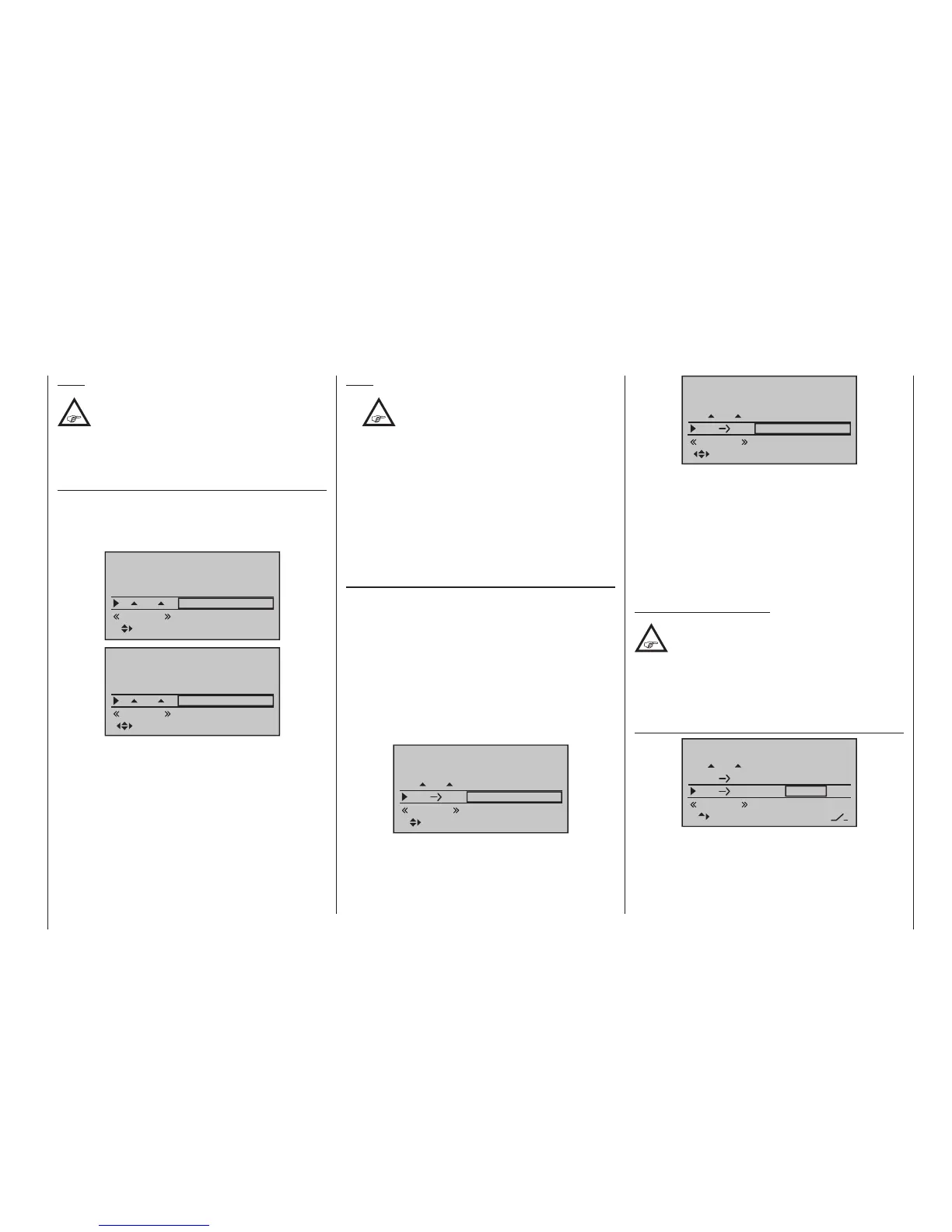
EL FL Off. (symm. elevator offset)
FL
0%
0%
fl.pos
EL FL 0%0%
0%
STO
normal
EL FL Off.
0%
–––
A value entered into the “EL FL” line offers support
to the elevator during tight curves and aerobatics.

 Loading...


