203
Program description - Free mixers
Trim Effect on mixer output
None linear over full trim lever travel
Forward Only effective if C1 stick is forward
Back Only effective if C1 stick is back
… or – in the case of model helicopters – in the “Thr.”
line of the »Stick mode« menu, which is available on
the
mc-20 HoTT transmitter only:
Trim Effect on mixer output
TA
(Thr-AR)
linear over full trim lever travel to output
6 (throttle servo)
TL
(Throttle
limit)
only effective at minimum position of
the assigned throttle limit control (the
right side proportional rotary control as
standard)
PT
(Pitch)
linear over full trim lever travel to control
function “Pitch”
Switching mixers in series
As already explained on page 200, you can also
switch mixers in series: Where mixers are switched
in “sequence”, the “input signal” of a control channel
already on its way to the servo “branches off” and is
directed to a further channel. In the “ty” column, select
the right angle bracket “
” or “Tr ”, if the trim should
also act simultaneously on the mixer input:
ty
fr
to
M1
M2
M3
6
7
7
8
M4
M5
??
??
??
??
??
??
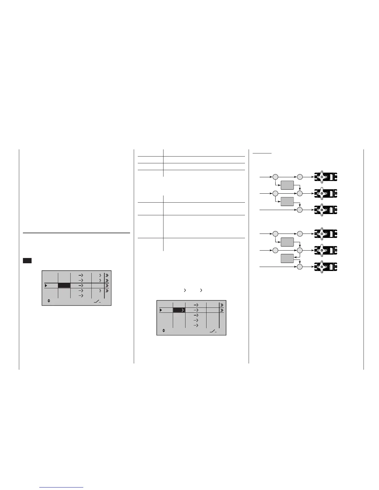
Example:
Two mixers (MIX 6 7 and 7 8):
a) WITHOUT series switching:
6 6
7
Servo
4,8 V
C 577
Best.-Nr. 4101
Servo
4,8 V
C 577
Best.-Nr. 4101
7
8
Servo
4,8 V
C 577
Best.-Nr. 4101
MIX 1
MIX 2
b) The same mixers WITH series switching:
6 6
7
Servo
4,8 V
C 577
Best.-Nr. 4101
Servo
4,8 V
C 577
Best.-Nr. 4101
7
8
Servo
4,8 V
C 577
Best.-Nr. 4101
MIX 1
MIX 2
In this highly simplified example, if mixer 2 is switched
in series, then it does not “take over” solely the trans-
mitter signal of control function 7 – as shown under
a) – but, instead, the entire (mixed) signal present at the
servo side of control channel 7, as shown under b).
It then directs this in accordance with its confi gured
mixer ratio forwards to control channel 8. In this case,
the effect of transmitter control “6” extends as far as
output “8”. This kind of serial linkage can be extended
as far as you wish. For example, another mixer “8
12” can be used to route the control signal from “6” as
far as output “12”, taking into consideration the associ-
ated mixer ratios. Of course, even with an active serial
link, each separate mixer can still be controlled via the
transmitter control assigned to the mixer input. Fixed-
wing and helicopter mixers also work in the same way,
A switch must be assigned to LinearMIX 4 if you wish
to switch between two fixed mixer values (still to be
set) that correspond to the two end-points of a (pro-
portional) transmitter control. Accordingly, the “switch
channel” mixer cannot also be switched “on” or “off” as
with the other mixers.
If you intend to assign a control switch (G1 … G4) or a
logical switch (L1 … 8) as the mixer switch, then please
remember that you also must define the switch as such
in the »Control switches« menu, or in the »Logical
switches« menu, which is available as standard on the
mc-20 HoTT transmitter only. If you do not, you will
assign an undefined control or logical switch and there-
fore one that functions as a fixed switch.
“Ty(pe)”
Including the trim
For control functions 1 … 4, you can also allow trim-
ming of the digital trim lever for the given stick effect
the mixer’s input. In this case, briefly tap the centre
SET key of the right four-way button then use the se-
lection keys to select “Tr” in the inverse video field:
ty
fr
to
M1
M2
M3
6
EL
C1
EL
M4
M5
3
8
S
EL
??
??
C4
4
2
Tr
The effect of the C1 trim lever on mixer output will
depend on the function assigned in the »Model type«
menu, page 98, in the “Motor on C1” column for
fixed-wing models …

 Loading...


