202
Program description - Free mixers
Erasing mixers
To erase a previously-defined mixer, select the ap-
propriate line with the selection keys on the left
or right four-way button, switch to the “fr” column, if
necessary, with the selection keys then briefly tap
the centre SET button on the right four-way button:
ty
fr
to
M1
M2
M3
6
EL
C1
EL
M4
M5
8
S
EL
??
??
Tr
C4
4
2
3
The field in the “fr“ column for the mixer you want to
delete will now be shown in inverse video: tap both
selection keys or on the right four-way button
at the same time (CLEAR):
Ty p
fr
zu
M1
M2
M3
6
EL
C1
EL
M4
M5
??
S
EL
??
??
C4
4
2
??
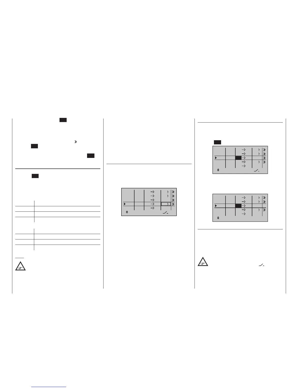
Mixer switches
In the sample screen image shown above, switches “4”
and “2” have been assigned to linear mixers 1 and 4
and to mixer 2 of the control switch “C4”.
The switch symbol to the right of the switch number
shows the current switch state.
Any mixers not assigned to a switch, as
indicated by an empty cell for the column
marked by the switch icon (“ ”) on the
screen’s bottom line, are fundamentally active!
To do this, tap the centre SET key of the right four-
way button once again and assign a switch as de-
scribed in the section “Physical control, switch and
control switch assignments” on page 60.
7. Using the selection key of the left or right four-
way button, switch to the column (“
”) then tap the
centre SET key of the right four-way button.
8. Define the mixer ratios on the second screen page.
9. Return to the first page by using the centre ESC
key of the left four-way button.
“fr(om)”
After selecting a mixer line and a subsequent tap on
the centre SET key of the right four-way button, select
one of the control functions, 1 … 8 respectively 1 …
12 or S, for the value field now in inverse video with the
selection keys of the right touch.
For the sake of clarity, control functions 1 … 4 are
marked as follows when setting wing mixers:
C1 Throttle/airbrake stick
AI Aileron stick
EL Elevator stick
RU Rudder stick
… and, for the helicopter program:
1 Throttle/collective pitch stick
2 Roll stick
3 Pitch-axis stick
4 Tail rotor stick
Note:
If you select any of the control functions 5 …
12 max. for xed-wing models or 5, 7 … 12
max. for helicopter models, do not forget to
assign a transmitter control for each of these in the
»Control adjust« menu!
“S” as switch channel
Selecting “S” (switch channel) in the “fr” column has
the effect of passing a constant input signal to the mix-
er input, e. g. in order to add a little more “up-elevator”
trim when the aero-tow release is closed, as mentioned
on the previous page.
After assigning a control function or the “S” switch
channel in the “fr” column, the following is also dis-
played …
“to”
… on the lower edge of the screen.
Use this column’s input field to specify the destination
of the mixer, i. e. assign mixer output, to one of the
control channels. At the same time, additional fields will
appear in the bottom line of the screen:
ty
fr
to
M1
M2
M3
6
EL
C1
EL
M4
M5
3
8
S
EL
??
??
C4
4
2
Tr
In this example, four mixers have already been defined.
The second mixer is already familiar in principle as
“Elevat curve” from the “Brake settings” sub-menu of
the »Wing mixers« menu and the third is familiar from
the line “Tail” (“2ELSv3+8”) of the »Model type« menu.
As a general rule, however, you should first make use
of the pre-programmed mixers. However, if you need
asymmetric mixer ratios, want to program non-linear
curves or need to offset the mixer neutral point, then
you should set or leave the pre-programmed mixers at
“0 %” and replace these with free mixers.

 Loading...


