239
Program description - Telemetry
The receiver temperature limit, at which a warning is
issued, can be adjusted in the sub-menu »RX SERVO
TEST« under “ALARM TEMP+” (50 … 80 °C and
“ALARM TEMP-” (-20 … +10 °C). When the value is
under-run or over-run, an acoustic signal sounds (con-
tinuous peep tone) and “TEMP.E” will appear at the
top right of all “RX” receiver sub-menus. Additionally,
the parameter “R-TEM” will be displayed in inverse
video on the »RX DATAVIEW« display page.
Data packages (L PACK TIME)
Indicates the longest time span in ms in which data
packages are lost in the transmission from the trans-
mitter to the receiver. In practice, that is the longest
time span in which the remove control system has
entered into fail-safe mode.
Receiver operating voltage (R-VOLT)
Always check the operating voltage of the receiver.
Never operate or even start your model if the operating
voltage is too low.
The receiver low voltage warning can be adjusted be-
tween 3.0 and 7.5 volts in “ALARM VOLT” of the »RX
SERVO TEST« sub-menu. If this range is under-run,
an acoustic signal is sounded (repetitive double peep
tone (long/short)) and “VOLT.E” will appear at the top
right of all »RX …« receiver sub-menus. In addition, the
parameter “R-VOLT” will be displayed in inverse video
in the »RX DATAVIEW« sub-menu.
The current receiver battery voltage is also displayed in
the main display, see page 30.
Minimum receiver operating voltage (L.R-VOLT)
“L.R-VOLT” indicates the minimum operating voltage of
the receiver since the last time it was switched on.
If this voltage should deviate significantly from the cur-
rent “R-VOLT” operating voltage, the receiver battery
may be too heavily encumbered by the servos. The
consequence is voltage drops. In this case, use a more
powerful voltage supply in order to achieve maximum
operational safety.
Sensor 1 + 2
Indicates the values of optional telemetric sensors 1
and 2, if present, in volts and °C.
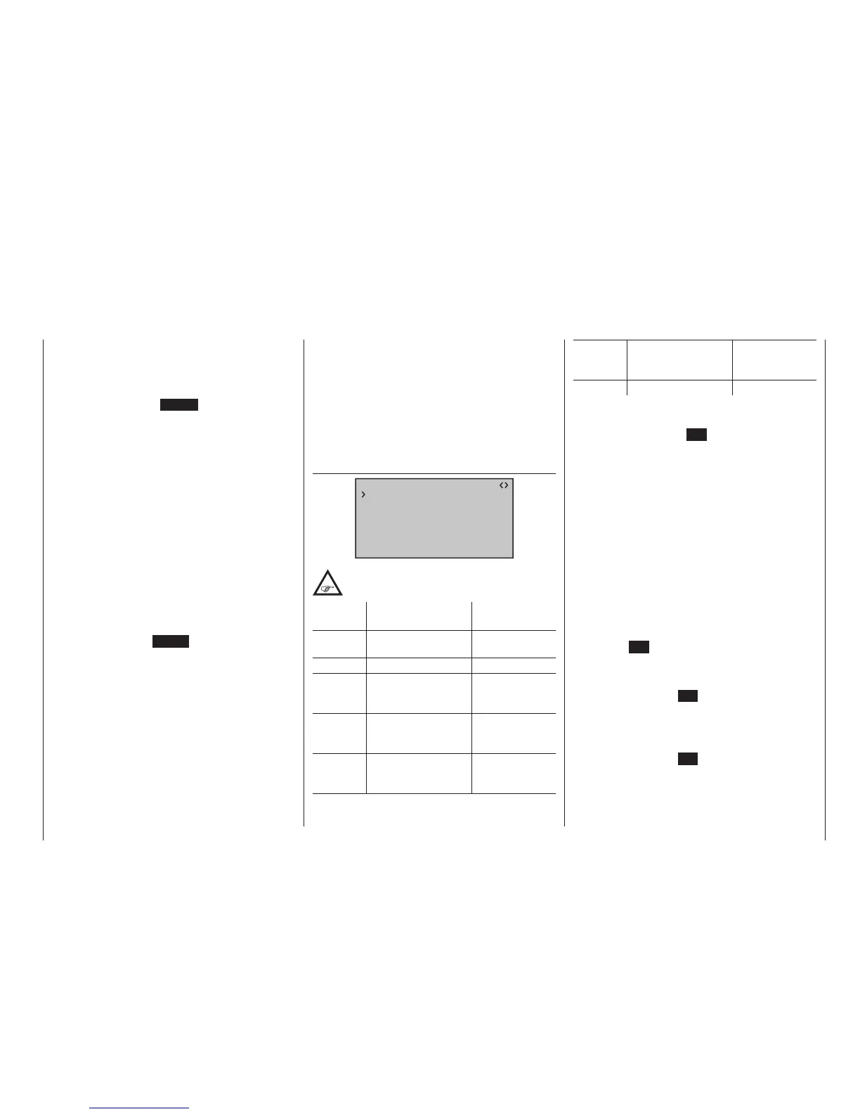
RX SERVO
RX SERVO V3.78
REVERSE : OFF
CENTER : 1500µsec
TRIM : –000µsec
LIMIT– : 150%
OUTPUT CH: 01
LIMIT+ : 150%
PERIOD : 20msec
It is very important that you read the notices
on page 236 before doing any programming
on this display page.
Value Explanation Possible
settings
OUTPUT
CH
Channel selection 1 … depending
on receiver
REVERSE Servo reversal OFF / ON
Centre Servo centre in µs if active (inverse),
dependent on
control position
TRIM Trim position in µs
deviating from the
Centre position
-120 … +120 µs
LIMIT– Travel limit on the "–"
side of servo travel in
% servo travel
30 … 150 %
LIMIT+ Travel limit on the "+"
side of servo travel in
% servo travel
30 … 150 %
PERIOD Cycle time in ms 10 or 20 ms
OUTPUT CH (channel selection)
If applicable, select the line “OUTPUT CH” with the
selection keys. Touch the SET key of the right four-way
button. The value field is shown highlighted. Now set
the desired channel (e. g. 01) with the selection keys on
the right four-way button. The following parameters
are always based on the channel set here.
Reverse (servo reversal)
Set the rotational direction of the servo connected to
the selected servo channel: ON / OFF
Centre (servo centre)
For the control channel selected in the “OUTPUT CH”
line, the “Centre” line displays the currently stored pulse
width for “servo centre” in μs. The default channel
pulse width of 1500 μs represents the standard centre
position, and corresponds to the usual servo centre
setting.
In order to change this value, select the “Centre” line
then tap the SET key of the right four-way button.
The Value field is highlighted. Now move the respec-
tive transmitter control, stick and/or trim lever to the
desired position and store the current control’s position
with another tap on the SET key. This position is saved
as the new neutral position.
The – new – value now displayed varies according to the
current setting of the transmitter control which affects
this control channel, and the position of its trim is saved
with another tap on the SET key.

 Loading...


