284
Programming examples - Winged models
Model type (page 98)
Tail type
Motor at C1
Normal
None
Aile/flaps
1AIL
Model type
Brake Off In 1+100%
SEL
… the principle arrangement of the servos in the model
is selected and communicated to the transmitter. The
following selections are available:
“Motor at C1”
• “none”
Trimming works independently of the stick position
and the “Brake settings” sub-menu of the »Wing
mixers« menu, beginning on page 166, is availa-
ble without limitation.
The “Throttle too high” warning message, see page
35 and/or 98, and the “Motor stop” option,
page 85, are deactivated.
• “(Idle) front or back“
C1 trimming is affected in the front or rear and the
“Motor stop”, page 85, option is activated.
If the throttle stick is too far in the full throttle direc-
tion when the transmitter is switched on, this will be
indicated with the warning message “Throttle too
high”.
In parallel with this, the “Brake settings” sub-menu
of the »Wing mixers« menu, beginning on page
166, will only then be available if the “Motor” co-
lumn of the »Phase settings« menu, page 148,
has the entry “none” for the currently active flight
phase.
In the next two lines, the principle arrangement of the
servos in the model is selected and communicated to
the transmitter:
+100%
SEL
Tail type
Motor at C1
Normal
None
Aile/flaps
1AIL
Model type
Brake Off In 1
• Tail type
“normal”, “V-tail”, “Delt/fl.wing” or “2 Sv EL 3+8”
• Aileron/camber aps
1 or 2 AIL servos and 0, 1 or 2 FL servos
in the 8 channels
mc-16 HoTT transmitter and 1,
2 or 4 AIL servos and 0, 1, 2 or 4 FL servos
in the 12 channels
mc-20 HoTT transmitter
Since we want to actuate the brake system of the
“Brake settings” sub-menu under the »Wing mixers«
menu with the C1 stick, we will leave the outer right
setting in the “Brake Offset” line with “Input 1”. With
the “Offset value” to the left of this, you should only
place the mixer neutral point at the point where the
brake system is retracted or inactive. If, in the process,
the offset is not place completely at the end of the
control path, the rest of the path is “idle travel”, which
means the mixer is not influenced in this range of the
stick movement. This free travel ensures that all brakes
remain even with slight deviations from the stop of the
airbrakes control in the neutral position. At the same
time the effective control travel is automatically spread
to 100%.
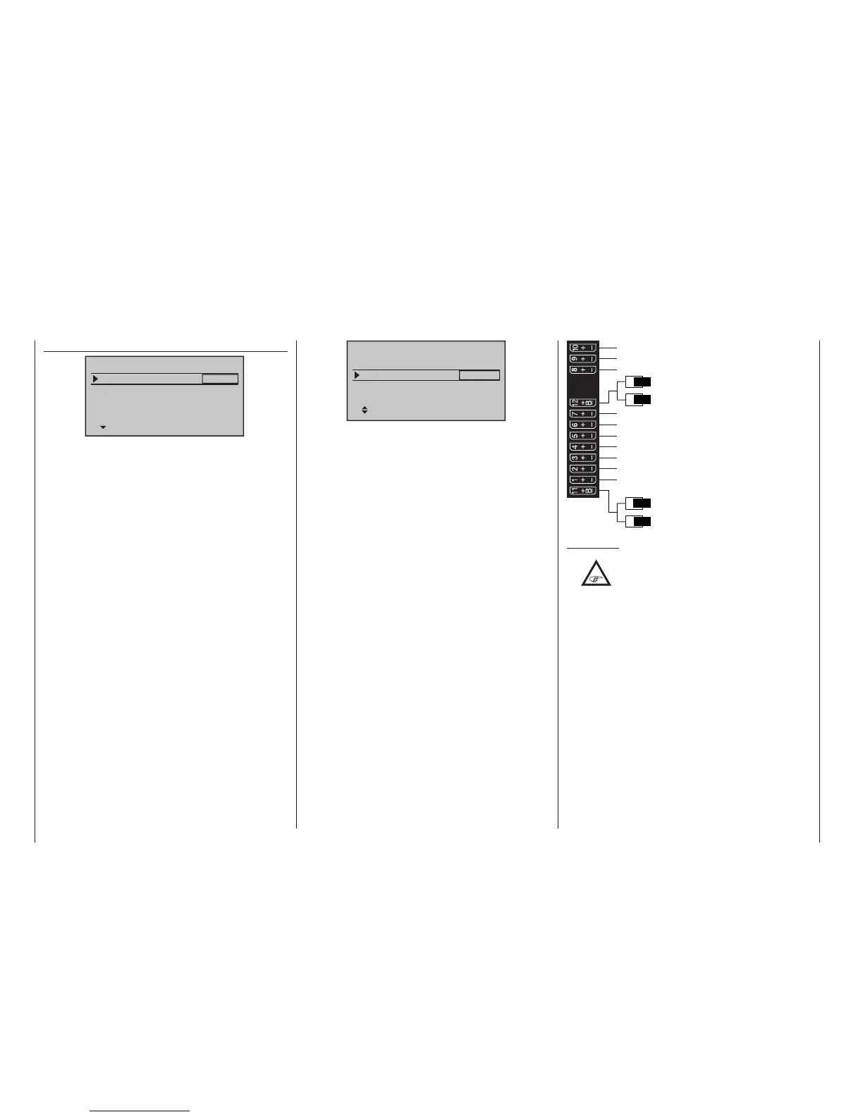
By now at the latest, servos should be plugged into the
receiver in the standard Graupner’ish sequence:
Receiver power supply
Free or left aileron 2 or aux. function
Free or right aileron 2 or aux. function
Rudder
Aileron or left aileron
Elevator or 1st elevator
Free or 2nd elevator or aux. function
Receiver power supply
Airbrake or throttle servo
or speed controller (electric motor)
Right aileron or aux. function
Flap or left flap
Right flap or free or aux. function
Free or left flap 2 or aux. function
Free or right flap 2 or aux. function
Comments:
•
If a V-tail unit should move incorrectly ei-
ther “high/low” or “left/right”, please ob-
serve the information in the table on page
65 in the right column. The same process ap-
plies for the ailerons and aps.
• If in a V-tail “elevator” and / or run “rudder” are
moving in the wrong direction, then please follow
the instructions in the table on page 65, right col-
umn. Is similar to, if necessary, to proceed with
the ailerons and aps.
• The settings described in the following are based
on a model with “normal” tail unit and “none (mo-
tor)”. The settings are adopted for models with a
V-tail with practically no changes at all. However,
the transfer of this information is not so simple for
delta/ying-wing models. Therefore, a special pro-
gramming example for this model type is provided
on page 312.
In the menu …

 Loading...


