301
Programming examples - Using ight phases
this given flight-phase is to be accomplished in order
to permit a “smooth” transition for different servo posi-
tions.
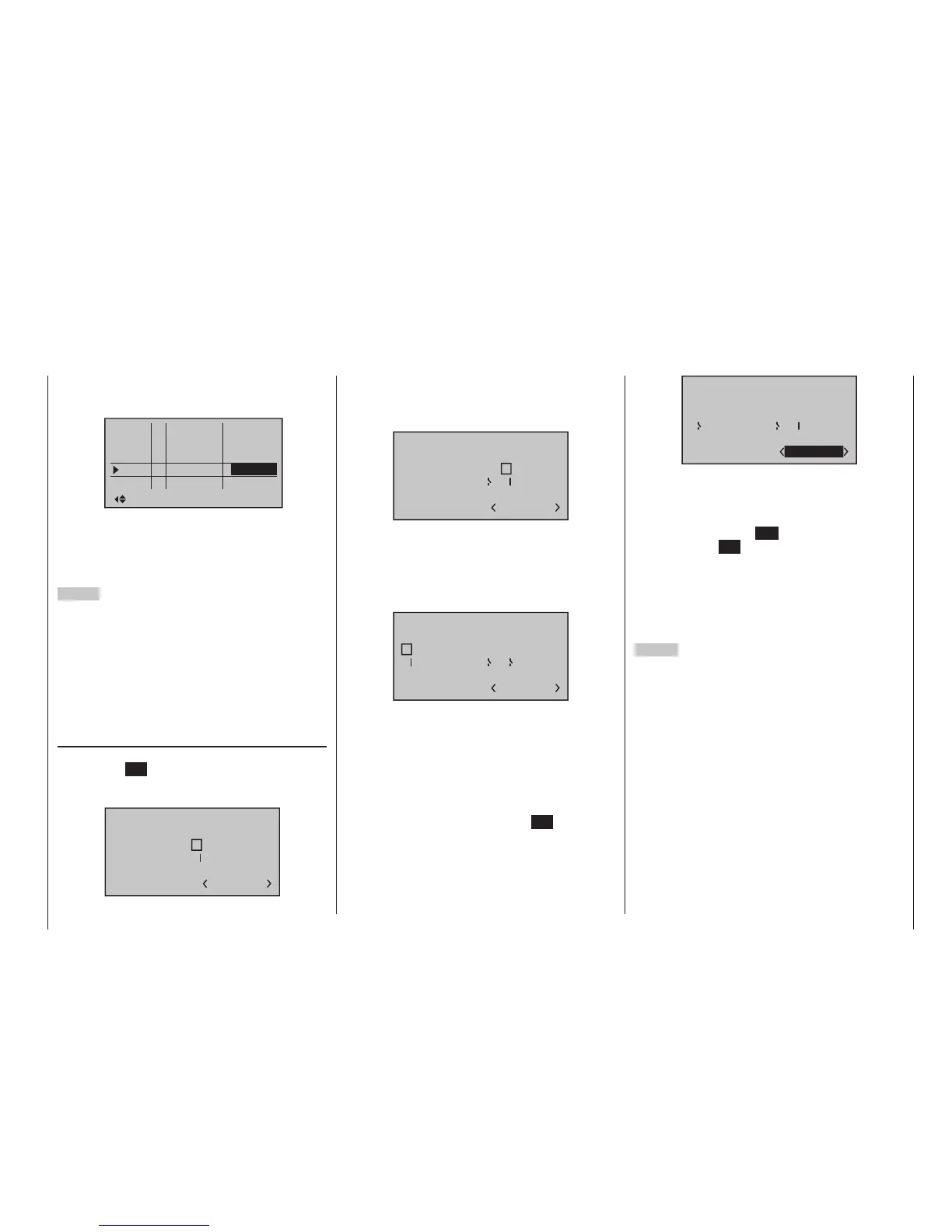
Pha1
Pha2
Pha3
Name Sw.time
Pha4
Pha5
+
+
normal
Thermal
Speed
+
–
3.0s
2.0s
4.0s
0.1s
Launch
1.0s
Thus, an increased stress of the model under certain
circumstances with a “hard” change of rudder or flap
positions, for example, is prevented. The “Status”
column shows you the currently active flight phase with
an asterisk “”.
2
nd
Step
In order to actually be able to switch between the indi-
vidual flight phases, the assignment of one or multiple
switches is necessary. Either one of the two three-way
switches is ideally suited for switching between up to
three flight phases.
Each of the two switch end positions starting from
the centre position will be assigned to one of the flight
phase switches A … F. The assignment of the switch
takes place in the menu …
»Phase assignment« (page 154)
First select “C” with the marker frame. Then briefly tap
on the centre SET key of the right four-way button and
move the switch from its centre position to one of its
end-positions, for example, forward:
Phase assignment
A B
C D E F
1 normal
2
6
7
prior
combi
Move the switch back to the centre position and then
select “D”, and after activation of the switch assign-
ment, move the switch to the other limit position, for
example, back:
A B
C D E F
1 normal
2
6
5
Phase assignment
prior
combi
Now the 3-way switch is programmed.
Now and additional switch could be assigned for the
“start” flight phase, if applicable. In this case under “A”,
so that the “start” phase is always switched to from
every other flight phase in parallel to the switching-on
of the motor:
A B
C D E F
1 normal
7
6
5
Phase assignment
prior
combi
The given switch positions must then be assigned to
respective flight phases (names). Although some flight
phases have already been assigned to names, the
phase name «1 Normal» will always initially appear at
the right in the display; see the figures above.
First move the 3-way switch to one of its limit positions,
for example to the back, and switch with the marker
frame in the display down to the right to set the flight
phase name. Briefly tap on the centre SET key of the
right four-way button to activate the entry field then
select the desired flight phase for this switch position,
in this example «2 Thermal», with the selection keys:
A B
C D E F
2
6
5
2 Thermal
7
Phase assignment
prior
combi
Proceed in the same manner for the other switch limit
position, which is assigned the name “3 Speed”.
If applicable move Switch 2 and assign this switch
combination the name “4 Start”.
A brief tap on the centre ESC of the left four-way but-
ton or the centre SET key of the right four-way button
will complete the phase name assignment.
The flight-phase dependent model settings made
before the assignment of phase switches are now in
the flight phase «1 Normal». This is the phase which is
called with the open «Start» switch in the centre posi-
tion of the 3-way switch.
3
rd
Step
In order to not have to carry out all previously made
settings for the model in the “new” flight phase from
the ground up, we recommend first copying the already
tested programming of the flight phase “Normal” to the
other flight phases. This is carried out in the menu …

 Loading...


