306
Programming examples - Using ight phases
• If you leave the Offset value at 0 %, the flaps
follow the travel of the elevator from the neutral
point of the elevator stick, at the percentage rate
set in the “EL FL” line.
• If you set an Offset value other than 0 %, the
flaps only follow the travel of the elevator in the
“down” and “up” direction after the elevator
command has reached the selected Offset point.
Now, within the »Wing mixers« menu, switch to the
“Brake settings” …
Elevat curve
Brake settings
QR
Crow
D.red
+44%
+77%
0%
+66%
0%
+55%
WK WK2
Note:
The “Brake settings” menu is switched “off” if:
“Motor on C1 forward / back” in the »Model
type« menu, page 98, AND the “Motor”
column of the »Phase settings« menu, page 148,
are set to “yes” for the currently active ight phase.
Change the ight phase, if applicable.
• Crow
In the menu “Model type” (page 100), we have set
the C1 stick for the airbrake control. Further above
in this text section, the C1 stick was set for brake
system steering.
In this line you determine the share with which the
AI and FL should be included on actuation of C1 in
the manner that both ailerons are deflected “slightly”
upward and both flaps are deflected as far down-
ward as possible.
Now with a simultaneous tap on the keys of
the left four-way button, a change to the »Servo
display« menu can be affected for observation of
servo movements and, in particular, to ensure that
no influence on the flaps takes place above the ad-
justed brake offset, e. g. +90 % and beyond to the
throw limit of the C1 control (“Idle travel” of the
C1stick).
• D.red
The value previously entered into the aileron differ-
entiation line should also be entered in this “Differ-
entiation reduction” line to fade this out during brak-
ing.
• Elevat. curve
This line is used for the entry of any correction fac-
tor that may be required for the elevator, see page
182.
Insofar as necessary, again check all flap throws and,
by way of the »Servo adjustment« menu (page 106),
adjust the servo centre, the servo travel and the travel
limit.
It may also be time to start the initial flight testing, inso-
far as all global settings – that is to say, all flight-phase
independent settings – are completed.
Two additional ight phases are now to be set up
below, each of which requires a somewhat differ-
ent ap position.
Therefore, switch to the menu …
»Phase settings« (page 148)
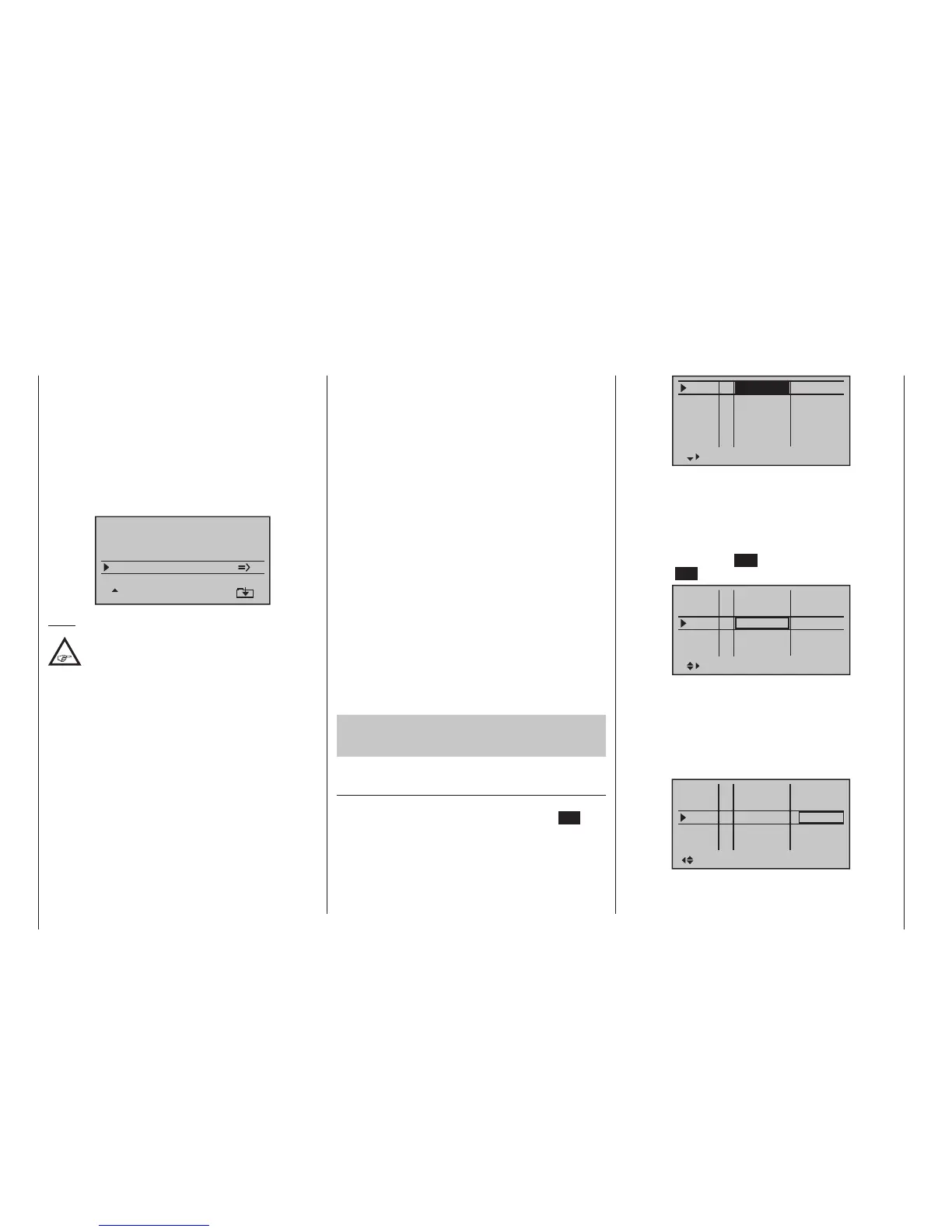
… and activate the assignment of phase names in the
“Name” column with a brief tap on the centre SET key
of the right four-way button:
Pha1
Pha2
Pha3
Name ph.Tim
Pha4
Pha5
normal
Start
Strecke
–
–
–
–
Now give Phase 1 – the “Normal phase” – that is also
the phase which includes the previous settings, the
name “Normal”, which you select from a list with the
selection keys.
Phase 2 is given the name “Thermal” and Phase 3 is
given the name “Speed”. Now conclude the entries
with a brief tap on the ESC key of the left four-way but-
ton or the SET key of the right four-way button:
Pha1
Pha2
Pha3
Name ph.Tim
Pha4
Pha5
normal
Thermal
Speed
–
–
–
–
Now move the marker frame beyond the “ph.Tim”
column to the right into the column “Sw. time” and set
a “switching time” from any other phase into the given
phase in order to avoid an abrupt phase change; in
other words to avoid erratic changes of flap positions.
Now try out different switching times. In this example
we have specified 1 s in each case:
Pha1
Pha2
Pha3
Name Sw.time
Pha4
Pha5
–
–
normal
Thermal
Speed
–
–
1.0s
1.0s
1.0s
0.1s
0.1s

 Loading...


