309
Programming examples - Using ight phases
–9%
fl.pos
AILE
Thermal
Diff.
+55%
Ail-tr
AI
+100%
+100%
• FL
Enter in this line the share of influence for ailer-
on and camber flap servos, when used as camber
flaps, is to be produced by the selected control (see
above) or 3-way switch. Be sure to set these values
low enough that the flaps can be controlled with ap-
propriate sensitivity, for example:
FL
–9%
+10%
fl.pos
+10%
AILE
Thermal
Diff.
+55%
Ail-tr
+100%
FL
–14%
+15%
fl.pos
+15%
FLAP
Thermal
Diff.
+33%
Ail-tr
+60%
A simultaneous tap on the or key combina-
tion of the right four-way button (CLEAR) will reset
changed values back to their standard default values.
Note:
Due to the improved lift distribution, the
degree of mix ratios should be set so that the
camber aps are slightly “lower” than the
ailerons.
With a simultaneous tap on the keys of the left
four-way button, the reaction of the AILE and FLAP
servos can be checked in the »Servo display« by
actuation of the selected camber flap control. (Push
the C1 stick to the front position so that the “AILE” and
“FLAP” positions can be better followed on actuation of
the corresponding control.)
Caution:
With aileron actuation the bars of the
»Servo display« move in the same man-
ner, for camber ap actuation they will
move in the opposite manner.
• In the control’s middle position, the – exam-
ple’s – “FL-pos.” setting only has a -9 % effect for
the AI and -11 % for the FL.
• In one transmitter control end-position, AILE and
FLAP are again closer to the neutral position be-
cause the mix ratio specified in the example reduc-
es the FL.pos setting, whereas …
• … in the other limit position, AILE and FLAP reach
the maximum downward offset prescribed by the
mixer percentage.
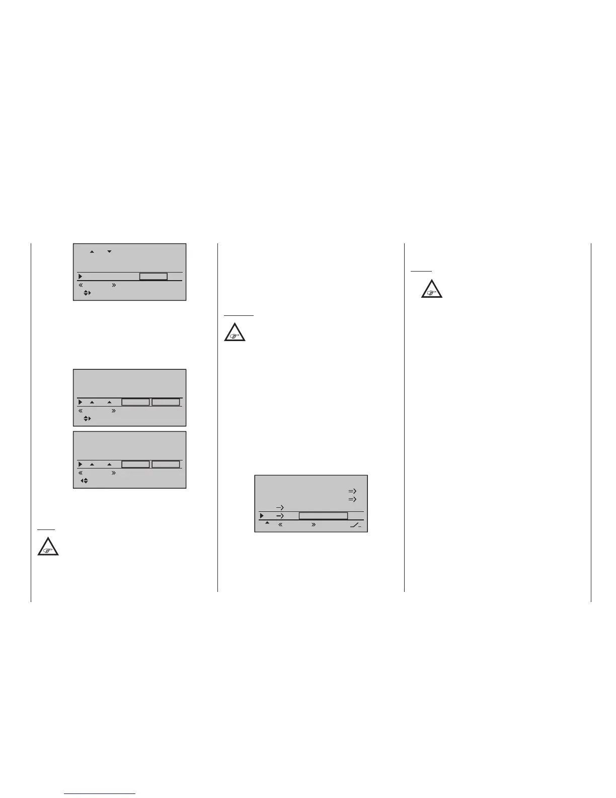
In order to set a – corrective – admix for the elevator, exit
the “Multi-flap menu” and return to the base screen of
the »Wing mixers« menu:
Brake settings
AI
0%
Wing mixer
FL EL +5%+5%
–––
–––
RU
Multi-flap menu
Thermal
In the two limit positions of the three-stage switch the
elevator is moved symmetrically in this example with
+5 % (true to side). If, on the other hand, you use a
proportional control, the elevator is deflected according
to the degree for the control position.
Then make the settings for the “Speed” flight phase in
the same manner.
Notes:
•
The digital trims for aileron, elevator and
rudder are always “phase-specic” in op-
eration at standard, regardless of these
settings.
• The current positions of the INC/DEC buttons,
CTL 5 + 6, which may be assigned to inputs 5
…8 or 5 … 12, are stored in accordance with your
preference entered in the “Type” line, i. e. the po-
sitions are not lost when you switch ight phases,
nor even when you change models.
The particular advantage of these two transmitter
controls – which are tted to the
mc-20 HoTT
transmitter only – lies in the fact that you can use
one and the same INC/DEC button as trim con-
trols in all the programmed ight phases, but – in
contrast to a position-related proportional con-
trol – the trim values are retained even if you
switch models.
• All settings vary by model. Make the settings on
your nished model or during the ight.

 Loading...


