308
Programming examples - Using ight phases
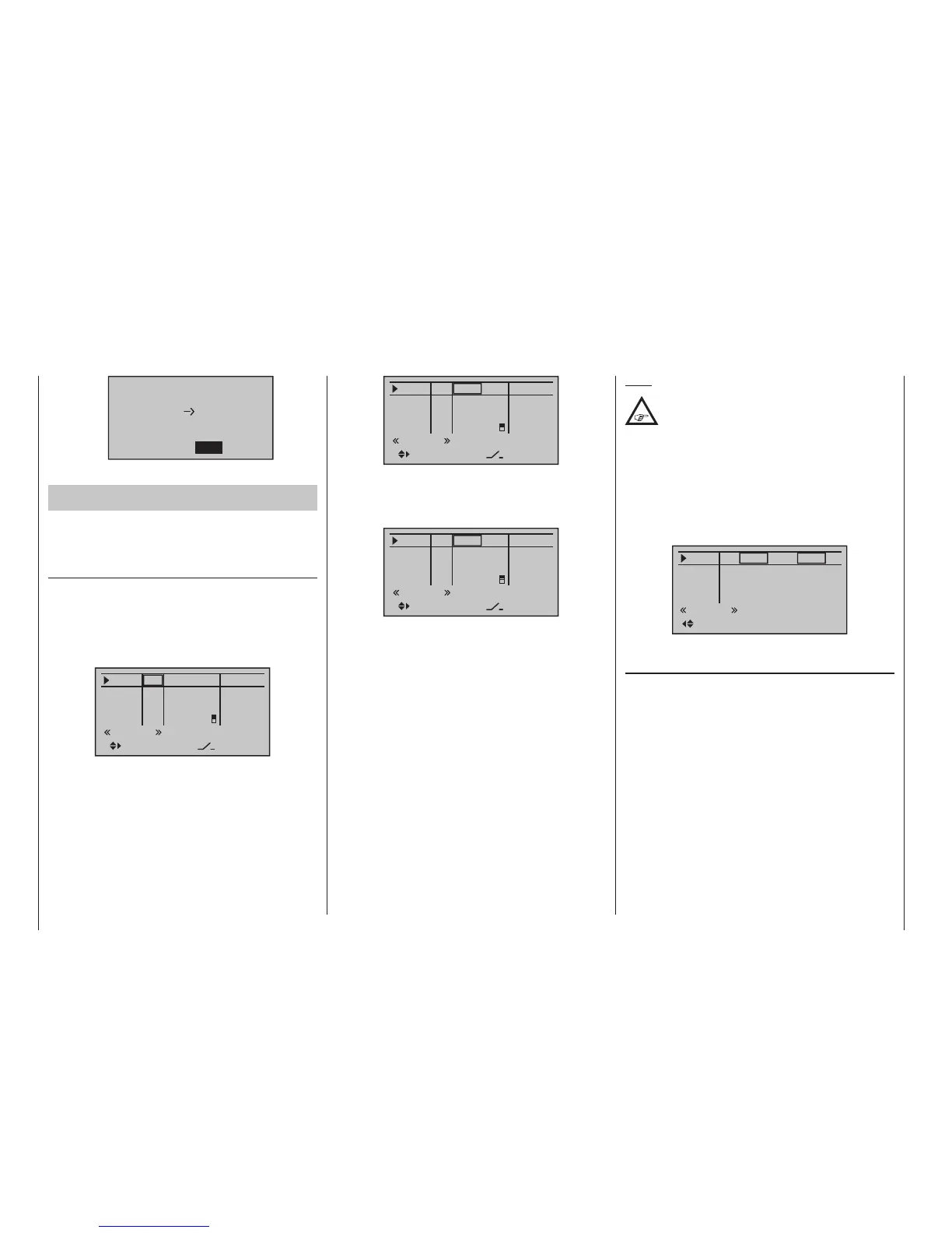
Phase to:
to be copied?
NO
1 Normal
2 Thermal
YES
Then repeat the process with flight phase “3 Speed”.
Now we will program the required settings in the
ight phase “Thermal” as an example.
In order to vary camber flap positions in the «Thermal»
phase, it is merely necessary to switch over to the
menu …
»Control adjust« (page 112)
… then change Input 6 – as described beginning on
page beginning on page 112 – from “GL(obal)” to
“PH(ase)” and finally assign it to an operating element.
To do this, first use the selection keys to switch into
the “typ” column for “In6” and change this setting from
“GL” to “PH”:
In6
offset
0%
0%
0%
–––
0%
In7
In8
In9
–––
–––
PH
GL
GL
GL
typ
Thermal
fr
fr
Cn1
8
–––
SEL
Thereafter change one column to the right into the
column above SEL …
In6
offset
0%
0%
0%
–––
0%
In7
In8
In9
–––
–––
PH
GL
GL
GL
typ
Thermal
fr
fr
Cn1
8
–––
SEL
… and now assign this input, as described in the sec-
tion “Physical control, switch and control switch as-
signments” on page 60, the left proportional slider in
the middle console to, for example:
In6
offset
0%
0%
0%
–––
0%
In7
In8
In9
–––
–––
PH
GL
GL
GL
typ
Thermal
Lv1
fr
Cn1
8
–––
SEL
This control will allow the ailerons (2+5) and camber
flaps (6 + 7) to be continuously adjusted (as camber
flaps) with a mixer ratio yet to be set via the »Wing
mixers« menu.
If you assign the still free second three-stage switch to
Input 6 instead, you can call three different FL positions
of the ailerons (AIL) and camber changing flaps (FL)
as well as three elevator positions (Elev) in the “Ther-
mal” flight phase, see the following page. (These three
switch positions correspond to the centre position
and the two limit positions of the previously mentioned
proportional rotary control.)
Note:
The FL and AIL ap positions in the two limit
switch positions or in the switch centre
depend on the value set in the column “- trv
+” as well as the offset value and the mixer proportion
set in the “Multi-ap menu” of the »Wing mixers«
menu, see further below.
Leave the (control) “- trv +” at its standard symmetric
settings of +100 % and the offset value at 0 %. Specify-
ing a symmetric or asymmetric time for smooth switch-
ing between the three switch positions – in the example
“1.2 s 1.2 s” – in the column “- time +” is recommended:
In6
– time +
1.2s
0.0s
0.0s
0.0s
In7
In8
In9
1.2s
0.0s
0.0s
0.0s
Thermal
In the “Multi-flap menu” of the …
»Wing mixers« (beginning on page 166)
… menu, subsequently change only the values for “FL.
pos” and “FL” in the «Thermal» flight phase:
• FL.pos
It is here that AILE and FLAP positioning takes
place during the «Thermal» flight phase in the event
that the assigned control (proportional control or
3-way switch) is in its neutral or middle position:

 Loading...


