317
Programming examples - F3A model
»Stick mode« (page 108)
… and reduce the number of trim steps in the “Tr”
column appropriately:
Ch.1
Aile
Elev
Tr
+
time
4
2
2
0.0s
0.0s
0.0s
0.0s
Rudd
0.0s
0.0s
0.0s
0.0s
GL
PH
PH
PH
St
2
It may also be necessary to assign appropriate operat-
ing elements and inputs for other model features, e. g.
retractable landing gear, fuel-mix, etc. Make these as-
signments with the …
»Control adjust« (page 112)
… menu where a specific input can be assigned to an
operating element, for example, the landing gear can
be assigned to an ON/OFF switch on Input 6 and the
fuel-mix can be assigned to one of the proportional
sliders in the middle console, e. g. the side-mounted
left proportional slider to Input 7. However, since it
involves flight-phase independent settings, leave the
standard default “GL” in the “typ” column:
0%
0%
0%
–––
0%
–––
–––
–––
GL
GL
GL
GL
normal
fr
Lv1
fr
SEL
In5
offset
In6
In7
In8
typ
3
The control travel of the operating elements must be
adapted and can also be reversed with a negative
travel setting.
Note:
For retractable landing a delay during opening
and closing can be specified that will not work
for the Landing Gear Servo C 713 MG, No.
3887.
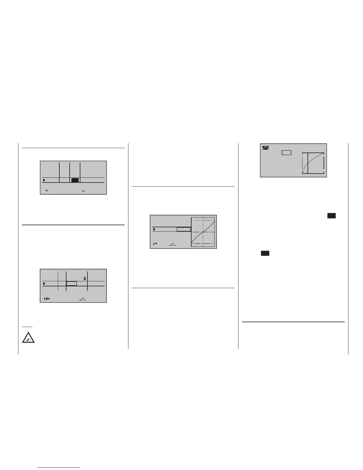
Input
Output
Point
1
–50%
0%
0%
Ch1 curve
normal
Curve
on
Only three interpolation points, “L” at -100 %, “H” at
+100 % and “1” at -50 % give the control travel the
rounded curve above.
Basic procedure:
• Move the C1 stick and, along with it the vertical line
in the graph display, toward idle to about -50 % of
control travel then briefly tap on the centre SET key
of the right touch pad.
• In order to attain the curve shape shown, raise this
point with the selection keys to approx. 0 % in the
inverse video value field in the “Point” line.
• Finally, round the characteristic curve by moving the
marker frame upward, select with a brief tap on the
centre SET key of the right touch pad then change
the value from “Off” to “On” with the selection keys.
If additional interpolation points between the left (“L”)
and right (“H”) end are necessary, repeat Steps 1 and 2
analogously.
Since F3A models normally have two aileron servos,
experience has shown that it is beneficial to move both
ailerons upward somewhat when landing. In the pro-
cess, the model usually approaches somewhat slower
and, above all, more steadily for the landing. In order
to do this it is necessary to program mixers through the
menu …
»Free mixers« (beginning on page 201)
… accordingly.
The ailerons are extended as landing assistance de-
pending on the position of the throttle stick, starting
from approximately half throttle toward idle. The further
the stick is moved toward idle, the more the ailerons
F3A models fly comparatively fast and thus react
“harshly” to the control movements of the servos. How-
ever, since small control movements and corrections
are not optically perceptible, because this results in
inevitable point deductions in competition, we recom-
mend setting an exponential control characteristic of
the stick. For this purpose, switch to the menu …
»Dual Rate / Expo« (page 126)
Experience has shown positive results with values of
approx. +30 % on the ailerons, elevator and rudders,
which you set in the right column with the selection
keys. In order to be able to control the F3A model to
run smoothly and cleanly:
+33%
+33%
+33%
Ail
Ele
Rud
EXPO
–––
–––
SEL
normal
–––
(Some experts even use up to a +60 % exponential
ratio.)
Since (some) combustion motors do not react linearly
to movements of the throttle stick, through the menu
…
»Channel 1 curve« (page 134)
… a “bowed” or, in other words, non-linear throt-
tle curve can be set. Four-stroke engine with Roots
pumps, in particular, such as OS Max FS 120, require a
steep ascension of the curve in the lower speed range.
However, the corresponding values must be adapted.
The C1 control curve for the motor could appear as
follows:

 Loading...


