325
Programming examples - Helicopter models
Input
Output
Point
1
0%
0%
Pitch
normal
Curve
off
0%
Always try to make due with these three points initially;
more points can “over-complicate” the matter and are
more of a burden at this point.
The reference point for the hovering should generally
be the mechanical centre position of the pitch stick,
because this position comes closest to the normal
control feel. Although the curve adjustment enables
other settings, you must know exactly what you are
doing. First set the pitch stick in the centre. The servos
which you had previously set according to manufac-
turer specifications have their levers at positioned per-
pendicularly to the servo housing (normally). A hovering
pitch value of 4 ° to 5 ° is now mechanically set at the
control rods to the rotor blades. In principle, all known
helicopters fly with this setting.
Then move the pitch stick towards maximum pitch until
the limit position. (The vertical line shows you the cur-
rent stick position.) Now change the pitch curve’s point
“H” with the selection keys of the right touch pad such
that the main rotor’s blades have a maximum pitch of
about 9 °. A value of +50 % should be about right:
Input
Output
Point
H
+100%
+50%
Pitch
normal
Curve
off
+50%
Note:
A rotor blade adjustment gage, such as the
Graupner pitch gage, No. 61, is quite useful
for reading the angle.
Now move the pitch stick toward the pitch minimum
position until its limit position. Depending on the abi-
lity of the pilot, adjust the value of point “L” so that the
blade angle of approach is 0 to -4 °. Now a slightly
pitched line arises at the hovering points, the so-called
pitch curve, which can appear as follows:
L
–100%
–75%
Pitch
normal
–75%
Input
Output
Point
Curve
off
Now you can, if you like, move the marker frame up-
ward with the selection keys to the “Curve” line and
after activation of the value field with a brief tap on the
centre SET key of the right touch pad, set the curve
function of the mixer to “on”.
L
–100%
–75%
Pitch
normal
–75%
on
Input
Output
Point
Curve
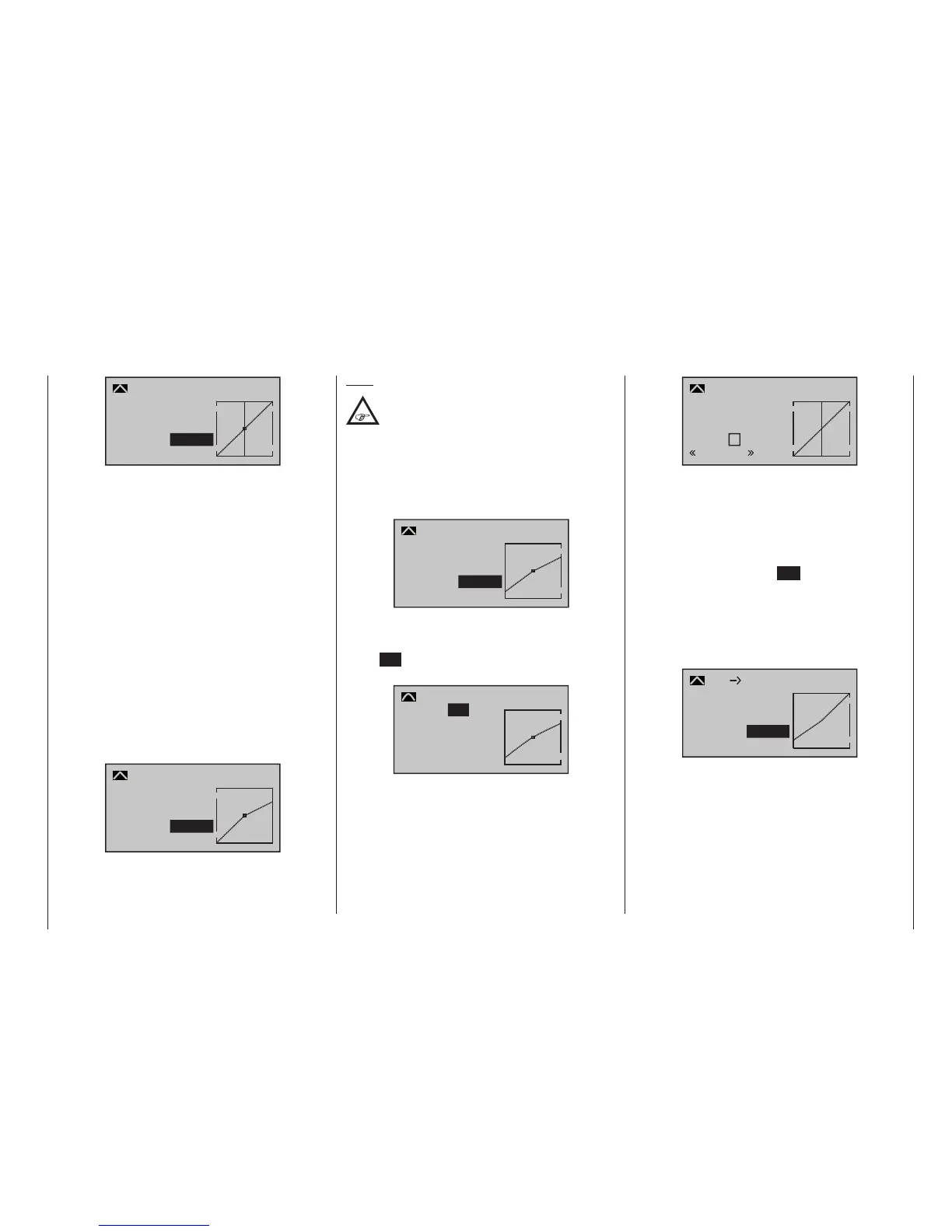
If you now switch to autorotation phase – at the bottom
left of the display the flight phase name “Autorot” ap-
pears – the “old” pitch curve is again:
?
0%
0%
0%
Pitch
Autorot
Input
Output
Point
Curve
off
Now carry out the same setting as before in the normal
phase. Only at point “H“ – at maximum pitch – is it pos-
sible to increase pitch angle by about 2 °. In doing so,
you will have somewhat more of an angle to catch the
model later on (!).
After setting pitch curve, move the autorotation switch
back then return to the helicopter mixer menu selection
with a brief tap on the centre ESC key of the left touch
pad. In that display, change to the “C1 Thro” line to
set the throttle curve.
The adjustment range for idle trim must first be
matched to the throttle curve. Do this by putting the
pitch stick into its minimum position then set point “L”
to about +15 %:
0%
+15%
C1
Thro
normal
L
+15%
Input
Output
Point
Curve
off
With the throttle limiter closed and idle trim completely
open, move the pitch stick back and forth somewhat at
the minimum limit position. The throttle servo may not
move with it in the process. No you have established
a seamless transition from the idle trim to the throttle
curve. The further settings along the throttle curve must
be carried out later in flight.

 Loading...


