324
Programming examples - Helicopter models
»Control adjust« (beginning on page 116)
In5
offset
Thro
Gyro
Lim.
–––
–––
–––
Lv2
0%
0%
0%
0%
GL
GL
GL
GL
typ
fr
fr
fr
–––
SEL
–––
0%
GL
fr
In8
… where input “Lim.” is assigned and all other inputs
are “fr(ee)” by default.
This “Lim.” input serves as the throttle limiter. Its
effect is exclusively on output “6”, where the throttle
servo is connected. The throttle limiter is assigned by
default to the right-side proportional rotary control.
•
In rmware versions up to and including
1102 the throttle limiter to the right side
proportional rotary slider SD2 is assigned
by default, as shown above. As of rmware ver-
sion 1103 is the input “Lim.” Default “free” and
consequently deactivates the throttle limiter func-
tion. To enable this feature, only needs to input
“Lim.” Another donor, for example, the original
proportional rotary slider SD2, are assigned.
Once again as a reminder:
•
With the use of the “throttle limiter” func-
tion, you do not have to program a ight
phase “throttle pre-selection”.
• The throttle limiter does not control the throttle ser-
vo; it only limits the travel of the throttle servo in
the full throttle direction according to its position.
The throttle servo is generally controlled from the
pitch stick via »Helicopter mixer« menu setting/s
for throttle curve/s, which is why input 6 must ab-
solutely remain “free”. Refer to pages beginning
on page 188 in this manual about this.
• The C1 trimming also affects only the throttle ser-
vo for the helicopter. At this point there is no need
to go into the particulars of this trimming once
again. Please read more about this on page 62.
(Thanks to the digital trimming, trim can be auto-
matically saved values with a model changeover
as well as with a change of the ight phase).
• A detailed description of the idle run base setup
model and the adjustment of idle and throttle limit
can be found beginning on page 122.
Then switch to the “travel” column with the selec-
tion key of the left or right touch pad and increase the
now inversely highlighted value from +100 % to +125 %
with a fully opened throttle limiter with a brief tap on the
centre SET key of the right touch pad:
– travel +
+100%
+100%
+100%
In11
Lim.
+100%
+100%
+100%
+100%
normal
+125%
In9
In10
In doing so, it is assured that the throttle limiter re-
leases the entire throttle travel with the pitch stick later
during flight.
Adjustment notice for electric helicopters:
Since electric drive systems have no need for
an idle setting, the basic conguration of
settings for an electrically-powered helicopter
merely involves ma king sure that the control range of
the throttle limiter is both higher and lower than the
adjustment range of the speed controller (usually
-100 % to +100 %) by a safe margin. If necessary,
therefore, the adjustment of the “travel” setting of the
throttle limiter described above must be modied
accordingly, for example, to symmetric +110 %. The
further adjustment, however, can take place analo-
gously to the combustion helicopter described here.
With this process, you have carried out the basic set-
tings for the transmitter as they are needed again later
for further model programming.
The actual helicopter-specific settings take place pri-
marily in the menu …
»Helicopter mixer« (beginning on page 184)
C1
C1
Pitch
Throttle
Tail
Tail
0%
Roll 0%
Throttle
Roll
Throttle
Tail
Nick
Nick
Throttle
Tail
Swash rotation
Swash limiter
0%
0%
0%
0°
OFF
normal
Gyro suppress
0%
Gyro gain
0%
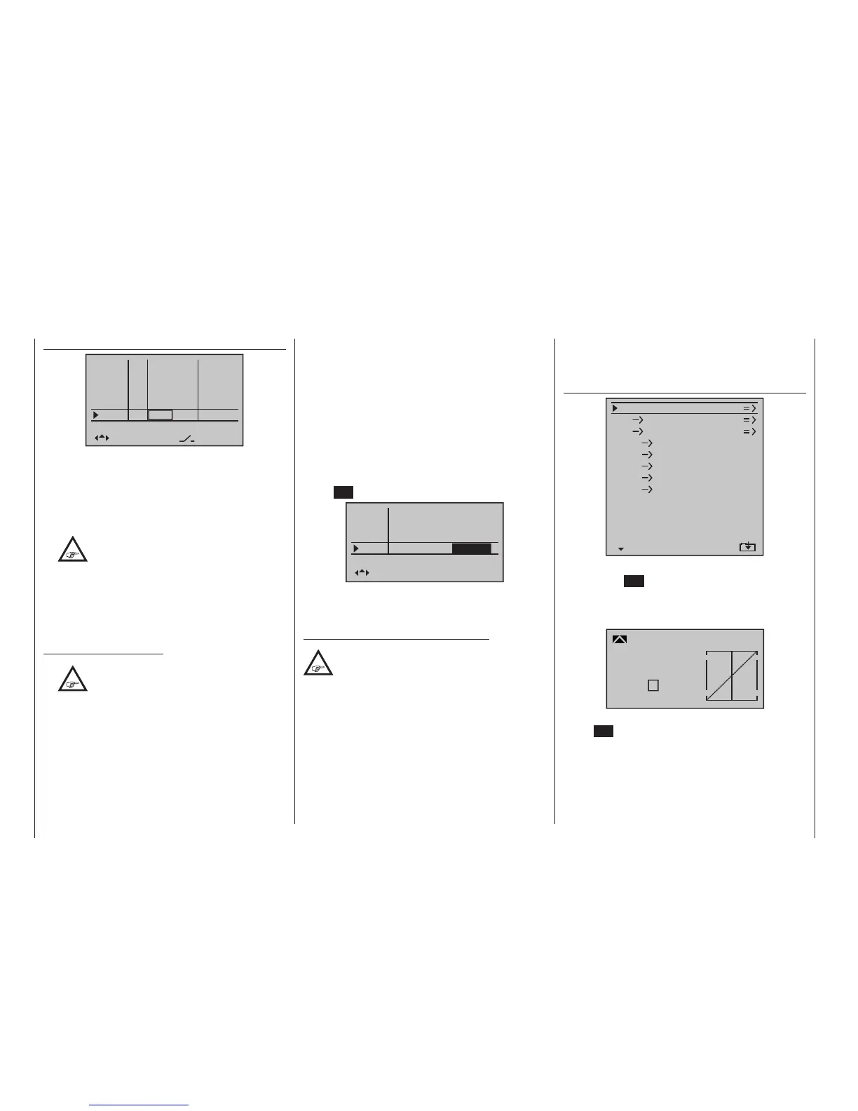
The “Pitch” function appears right in the first line. A tap
on the centre SET key of the right touch pad will cause
a switch to the corresponding sub-menu. The graphic
representation of the pitch curve appears here; it is
initially only defined by the points “L” and “H”:
Input
Output
Point
?
0%
0%
0%
Pitch
normal
Curve
off
Now place point “1” in the centre with a brief tap on the
centre SET key of the right touch pad:

 Loading...


