323
Programming examples - Helicopter models
3Sv(2rol)
SEL
Linear. swashpl.
Swashplate
no
Rotor direct
right
Heli type
Pitch min. back
“Expo throttle lim.” in the bottom line of this display,
are currently of no interest.
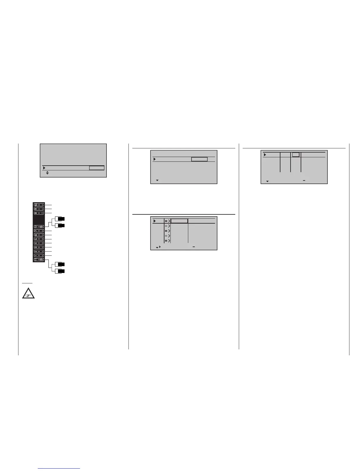
By now, the servos should be plugged into the recei ver
in the intended sequence:
Receiver power supply
Free or aux. function
Free or aux. function
Tail rotor servo (gyro system)
Roll 1 servo
Pitch-axis 1 servo
Free or speed governor or aux. function
Receiver power supply
Collective pitch or roll 2 or
Pitch-axis 2 servo
Free or aux. function
Throttle servo or speed controller
Gyro gain
Free or aux. function
Free or aux. function
Note:
Please note that on the newer Graupner mc
and mx remote control systems, the rst
pitch servo and the throttle servo are
swapped in comparison to some older systems.
Mix ratios and mix directions for swashplate pitch, roll
and nick servos are already pre-adjusted to +61 % in
the menu …
»Swashplate mixer« (page 216)
Swashplate mixer
Pitch
Roll
Nick
+61%
+61%
+61%
SEL
If the swashplate mixer should not follow stick move-
ments properly, first change the mixing directions from
“+” to “-” before changing servo directions in the menu
…
»Servo adjustment« (page 106)
S1
S2
S3
Rev cent
+
trv
0%
0%
0%
100%
100%
100%
100%
100%
100%
0%
0%
100%
100%
100%
100%
S4
S5
This menu can also be used to adapt travel and direc-
tion for individual servos. However, one must attempt
to retain 100 % servo travel so as to achieve the best
possible resolution and control accuracy. The direction
of travel is determined with “Rev.” and, in the process,
make sure that the direction is correct. The tail rotor
servo must run so that the nose (!) of the helicopter fol-
lows the tail stick direction.
In the following menu…
»Stick mode« (page 110)
Thr.
Roll
Nick
Tr
+
time
4
4
4
0.0s
0.0s
0.0s
4
0.0s
Tail
0.0s
0.0s
0.0s
0.0s
TL
PH
PH
PH
St
… of the mc 20 HoTT transmitter the column “Tr”
is used to set the increment size of each “click” on the
digital trim keys.
The C1 trimming only affects the throttle servo for the
helicopter. At this point there is no need to go into the
particulars of this trimming (“cut-off trim”) once again.
Please read more about this on page 62. (Thanks
to digital trimming, trim values can be saved automati-
cally when a model change is affected. In the
mc-16
HoTT and mc-20 HoTT systems these can even
be stored automatically when a change of flight phase
takes place.)
An additional setting which is specific to helicopters
can also be made in this menu in which you deter-
mine which function the trim lever on the pitch stick
should have. This is accomplished by selecting the
“TL” setting in the “Thr(ottle)” line or leaving it as it is.
This roughly corresponds to trim for the familiar idle
trim function. If the trim indicator marker is moved all
the way forward by “turning” the trim lever (remember:
“pitch min rear” = “throttle forward”) the throttle limit will
later take over the throttle limit for throttle enable seam-
lessly in the menu …

 Loading...


