92
Program description - Base setup models | Helicopter models
“BIND” column
1
BD
STARLET
SP channel 6
S P.
Mod
Mod.name
Stick mode
module
Base setup model
1 BIND
The “BIND” column in the right-hand column can be
used to initiate the “Bind” process of the non-Graupner
system – the transmitter’s RF section must be
switched off when the transmitter is rst switched
on.
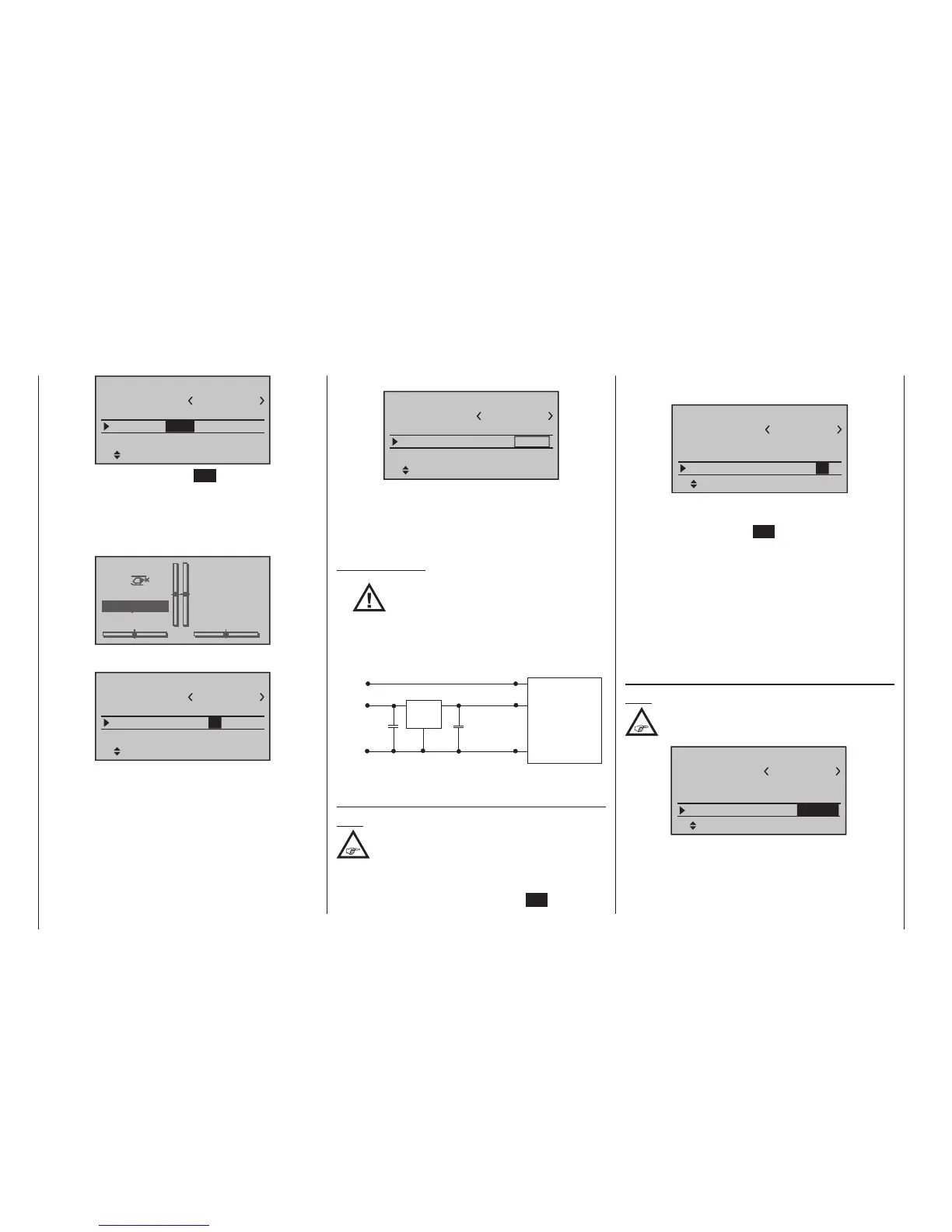
Important notes:
•
The output voltage of the DATA socket
is around 5 V, and must be reduced to
the power supply voltage generally re-
quired by external digital RF modules (3 to
max. 3.3 V). This is accomplished using the cir-
cuit which is shown here in diagrammatic
form:
GND
Vcc IN = 5 V
DATA +
DATA S
125000 baud signal
Vcc
GND
DATA -
22µF/6.3 V
22µF/6.3 V
Vcc OUT = 3 ... 3.3 V
Low Drop
Voltage
Regulator
SP.-MODULE
with
digital input signal
• Servo travels must be limited to max. 128 %.
SP channels
Note:
This menu line is suppressed in the “Module”
line if you select “HoTT” or “EXT.”.
If necessary, use the Select buttons of the left or
right-hand four-way button to move to the “SP chan-
nels” line, then briefly press the central SET button of
the right-hand four-way button to activate the Value
window:
1
SEL
STARLET
SP channel
S P.
Mod.name
Stick mode
module
Base setup model
1 BIND
6
You can now select “6” or “8” channels using the right-
hand Select buttons. The procedure is concluded by
again pressing the central SET button of the right-hand
four-way button.
At the transmitter this selection only affects the number
of control channels transferred to the external RF mod-
ule via the DATA socket. If you choose “6”, then these
are control channels 1 … 6; if you choose “8”, these
are channels 1 … 8.
Simultaneously pressing the or buttons of the
right-hand four-way button (CLEAR) returns the dis-
play to “6”.
EXT. PPM signal
Note:
This menu line is suppressed in the “Module”
line if you select “HoTT”.
1
PPM10
STARLET
EXT.PPM sig.
Mod.name
Stick mode
module
Base setup model
EXT.
SEL
normal
SEL
Some RF modules which can be connected to the
DSC connector require an inverted input signal. Be
sure to follow the respective module’s installation in-
structions for this.
1
BD
STARLET
SP channel 6
S P.
BIND1
Mod
Mod.name
Stick mode
module
Base setup model
Once again, press the central SET button of the right-
hand four-way button to conclude the Select process.
The lines of the “Receiver output” and “Range test” op-
tions (described below) are also suppressed, as are all
the HoTT-specific displays in the base display; “SP.” is
also superimposed instead of “HoTT”:
STARLET
#02
0:12h
Stp
Flt
«normal »
K78
0:00
0:00
4.1V
SP
“Mode” column
1
BD
STARLET
SP channel 6
S P.
BIND
Mod
Mod.name
Stick mode
module
Base setup model
1
In this column you select the transmission mode of the
external RF module:
• Mode “1”: 2-channel hopping
• Mode “2”: x-channel hopping

 Loading...


