2-1
2 Isolate-User-VLAN Configuration
When configuring an isolate-user VLAN, go to these sections for information you are interested in:
z Overview
z Configuring Isolate-User-VLAN
z Displaying and Maintaining Isolate-User-VLAN
z Isolate-User-VLAN Configuration Example
Overview
An isolate-user-VLAN adopts a two-tier VLAN structure. In this approach, two types of VLANs,
isolate-user-VLAN and secondary VLAN, are configured on the same device.
The following are the characteristics of the isolate-user-VLAN implementation:
z Isolate-user-VLANs are mainly used for upstream data exchange. An isolate-user-VLAN can be
associated with multiple secondary VLANs. As the upstream device is aware of only the
isolate-user-VLAN but not the secondary VLANs, network configuration is simplified and VLAN
resources are saved.
z You can isolate the Layer 2 traffic of different users by assigning the ports connected to them to
different secondary VLANs. To enable communication between secondary VLANs associated with
the same isolate-user-VLAN, you can enable local proxy ARP on the upstream device to realize
Layer 3 communication between the secondary VLANs.
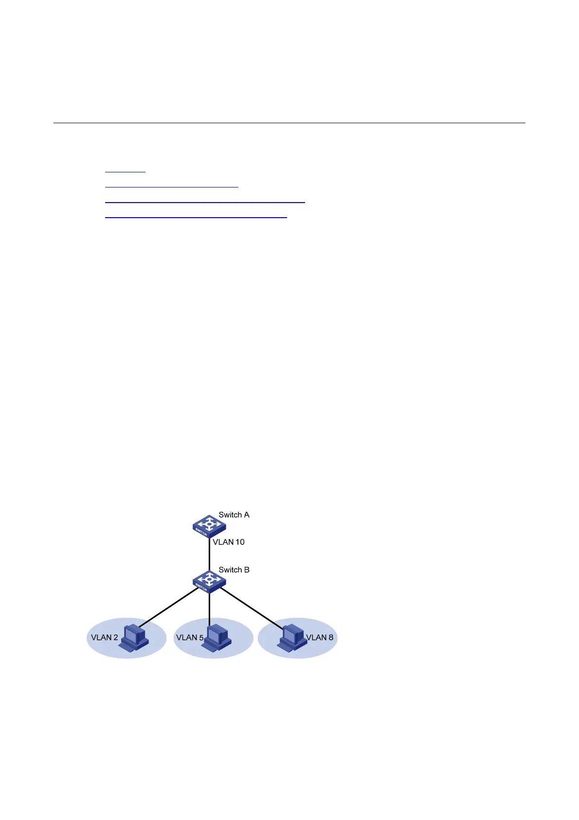
As illustrated in the following figure, the isolate-user-VLAN function is enabled on Switch B. VLAN 10 is
the isolate-user-VLAN, and VLAN 2, VLAN 5, and VLAN 8 are secondary VLANs associated with VLAN
10 and are invisible to Switch A.
Figure 2-1 An isolate-user-VLAN example
Configuring Isolate-User-VLAN
Configure the isolate-user-VLAN through the following steps:
1) Configure the isolate-user-VLAN;
2) Configure the secondary VLANs;

 Loading...


