1-10
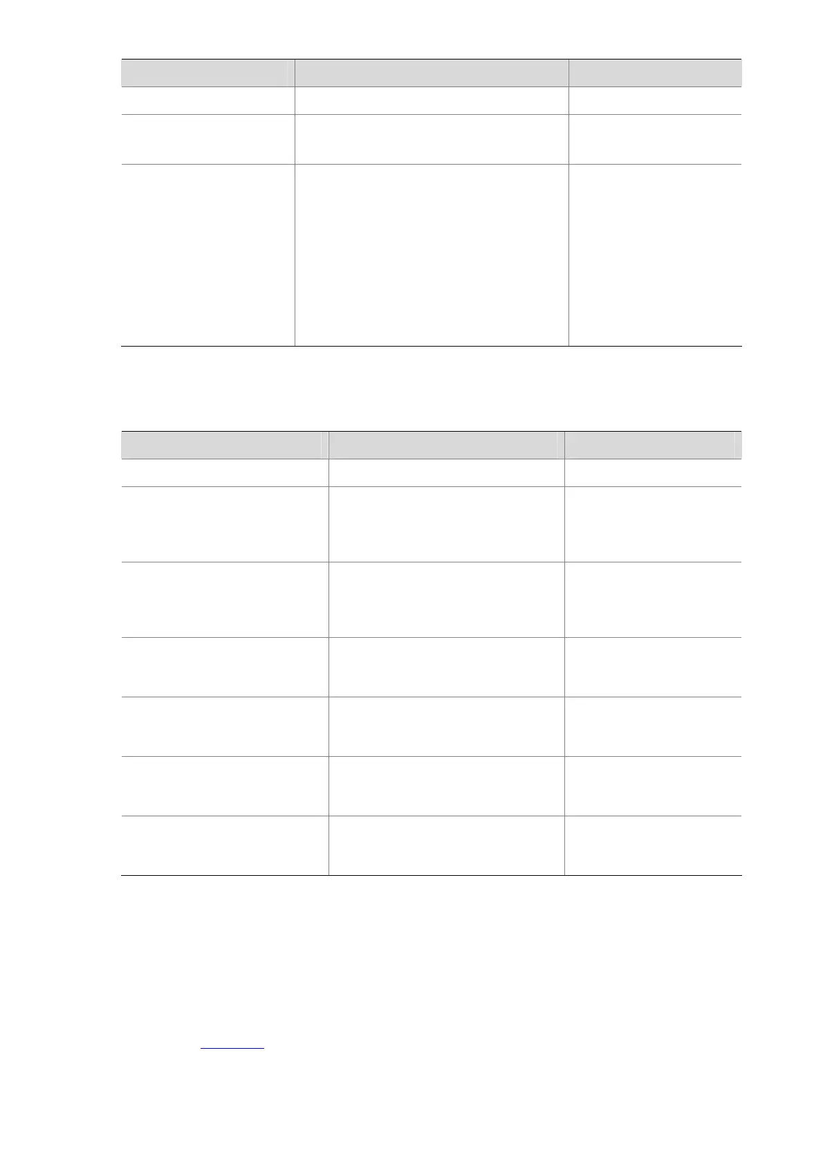
To do… Use the command… Remarks
Enter system view
system-view
—
Enter Layer 2 aggregate
interface view
interface bridge-aggregation
interface-number
—
Configure the load
sharing mode for the
aggregation group
link-aggregation load-sharing mode
{ destination-ip | destination-mac |
source-ip | source-mac } *
Required
By default, the load
sharing mode of an
aggregation group is the
global load sharing mode.
After you configure this
command, the load
sharing modes in current
link aggregation group
change accordingly.
Displaying and Maintaining Link Aggregation
To do... Use the command... Remarks
Display the local system ID
display lacp system-id
Available in any view
Display the global or
aggregation group-specific load
sharing mode
display link-aggregation
load-sharing mode [ interface
[ bridge-aggregation
interface-number ] ]
Available in any view
Display link aggregation details
of ports
display link-aggregation
member-port [ interface-type
interface-number [ to interface-type
interface-number ] ]
Available in any view
Display the summary
information of all aggregation
groups
display link-aggregation
summary
Available in any view
Display detailed information of
aggregation groups
display link-aggregation verbose
[ bridge-aggregation
[ interface-number ] ]
Available in any view
Clear the LACP statistics of
ports
reset lacp statistics [ interface
interface-type interface-number [ to
interface-type interface-number ] ]
Available in user view
Clear the statistics of the
specified aggregate interfaces
reset counters interface
[ bridge-aggregation
[ interface-number ] ]
Available in user view
Link Aggregation Configuration Examples
Layer 2 Static Aggregation Configuration Example
Network requirements
As shown in Figure 1-1, Device A and Device B are connected through their respective Ethernet ports
GigabitEthernet1/0/1 to GigabitEthernet1/0/3.

 Loading...


