List of Figures
© 2011 Harmonic Inc. 10 ProView 7000 v.2.4, Rev. A
Figure 4–38: Decoding Channel Properties – Video tab . . . . . . . . . . . . . . . . . . . . . . . . . . . . . . . 119
Figure 4–39: Decoding Channel Properties – PCR tab . . . . . . . . . . . . . . . . . . . . . . . . . . . . . . . . 121
Figure 4–40: Decoding Channel Properties – Audio tab. . . . . . . . . . . . . . . . . . . . . . . . . . . . . . . 122
Figure 4–41: Decoding Channel Properties dialog – VBI/VANC tab . . . . . . . . . . . . . . . . . . . . . 123
Figure 4–42: Decoding Channel Properties - OSD tab . . . . . . . . . . . . . . . . . . . . . . . . . . . . . . . . 126
Figure 4–43: Decoding Channel Properties - Status tab . . . . . . . . . . . . . . . . . . . . . . . . . . . . . . 127
Figure 4–44: GbE Port Properties (Output mode) dialog- General tab . . . . . . . . . . . . . . . . . . . 129
Figure 4–45: GbE Port Properties (Output mode) dialog - Advanced tab . . . . . . . . . . . . . . . . . 129
Figure 4–46: GbE Socket Properties (Output mode) dialog- General tab . . . . . . . . . . . . . . . . . 130
Figure 4–47: GbE Socket Properties (Output mode) dialog- Advanced tab . . . . . . . . . . . . . . . 131
Figure 4–48: TS Cross Connect. . . . . . . . . . . . . . . . . . . . . . . . . . . . . . . . . . . . . . . . . . . . . . . . . . . 132
Figure 4–49: Dynamic Program Cross Connection . . . . . . . . . . . . . . . . . . . . . . . . . . . . . . . . . . . 134
Figure 4–50: CAT EMM Cross Connect . . . . . . . . . . . . . . . . . . . . . . . . . . . . . . . . . . . . . . . . . . . . 134
Figure 4–51: Unreferenced PID Cross Connect . . . . . . . . . . . . . . . . . . . . . . . . . . . . . . . . . . . . . . 135
Figure 4–52: Set Decoder Channel. . . . . . . . . . . . . . . . . . . . . . . . . . . . . . . . . . . . . . . . . . . . . . . . 138
Figure 4–53: CAM Slot properties . . . . . . . . . . . . . . . . . . . . . . . . . . . . . . . . . . . . . . . . . . . . . . . . 140
Figure 4–54: Connection Wizard dialog . . . . . . . . . . . . . . . . . . . . . . . . . . . . . . . . . . . . . . . . . . . 141
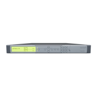
Figure 5–1: ProView 7000 front panel. . . . . . . . . . . . . . . . . . . . . . . . . . . . . . . . . . . . . . . . . . . . 144
Figure 5–2: ProView 7000 front panel menu tree structure . . . . . . . . . . . . . . . . . . . . . . . . . . 148
Figure B–1: ProView 7000 Decoder Rear Panel. . . . . . . . . . . . . . . . . . . . . . . . . . . . . . . . . . . . . 182
Figure B–2: D-Sub 15 Pinouts . . . . . . . . . . . . . . . . . . . . . . . . . . . . . . . . . . . . . . . . . . . . . . . . . . 184