List of Figures
© 2011 Harmonic Inc. 9 ProView 7000 v.2.4, Rev. A
List of Figures
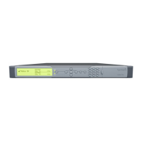
Figure 1–1: ProView 7000 Platform General View . . . . . . . . . . . . . . . . . . . . . . . . . . . . . . . . . . . 16
Figure 2–1: ProView 7000 with the DVB-CI module and Smart Card. . . . . . . . . . . . . . . . . . . . 21
Figure 2–2: AC Connector. . . . . . . . . . . . . . . . . . . . . . . . . . . . . . . . . . . . . . . . . . . . . . . . . . . . . . . 21
Figure 2–3: Front Panel startup display. . . . . . . . . . . . . . . . . . . . . . . . . . . . . . . . . . . . . . . . . . . . 23
Figure 3–1: EMS Window . . . . . . . . . . . . . . . . . . . . . . . . . . . . . . . . . . . . . . . . . . . . . . . . . . . . . . . 27
Figure 3–2: Selecting Low Delay Mode . . . . . . . . . . . . . . . . . . . . . . . . . . . . . . . . . . . . . . . . . . . . 39
Figure 4–1: ProView 7000 EMS Graphical User Interface . . . . . . . . . . . . . . . . . . . . . . . . . . . . . 41
Figure 4–2: Alarm tab . . . . . . . . . . . . . . . . . . . . . . . . . . . . . . . . . . . . . . . . . . . . . . . . . . . . . . . . . . 43
Figure 4–3: EMS toolbar . . . . . . . . . . . . . . . . . . . . . . . . . . . . . . . . . . . . . . . . . . . . . . . . . . . . . . . . 45
Figure 4–4: EMS menu bar . . . . . . . . . . . . . . . . . . . . . . . . . . . . . . . . . . . . . . . . . . . . . . . . . . . . . . 47
Figure 4–5: Device tooltip. . . . . . . . . . . . . . . . . . . . . . . . . . . . . . . . . . . . . . . . . . . . . . . . . . . . . . . 51
Figure 4–6: Device context menu. . . . . . . . . . . . . . . . . . . . . . . . . . . . . . . . . . . . . . . . . . . . . . . . . 52
Figure 4–7: Add Device dialog . . . . . . . . . . . . . . . . . . . . . . . . . . . . . . . . . . . . . . . . . . . . . . . . . . . 54
Figure 4–8: Presets Management dialog . . . . . . . . . . . . . . . . . . . . . . . . . . . . . . . . . . . . . . . . . . . 58
Figure 4–9: Backup and Restore Configuration dialog. . . . . . . . . . . . . . . . . . . . . . . . . . . . . . . . 61
Figure 4–10: Device Explorer tab . . . . . . . . . . . . . . . . . . . . . . . . . . . . . . . . . . . . . . . . . . . . . . . . . . 64
Figure 4–11: Physical Input box hierarchy . . . . . . . . . . . . . . . . . . . . . . . . . . . . . . . . . . . . . . . . . . 68
Figure 4–12: Physical Output box . . . . . . . . . . . . . . . . . . . . . . . . . . . . . . . . . . . . . . . . . . . . . . . . . 80
Figure 4–13: Device properties dialog – Network tab . . . . . . . . . . . . . . . . . . . . . . . . . . . . . . . . . 82
Figure 4–14: Device properties dialog – Hardware – Platform tab . . . . . . . . . . . . . . . . . . . . . . . 84
Figure 4–15: Device properties dialog – Hardware – Main Board tab . . . . . . . . . . . . . . . . . . . . 85
Figure 4–16: Device properties dialog – Hardware – Front End tab . . . . . . . . . . . . . . . . . . . . . . 86
Figure 4–17: Device properties dialog – Hardware – Bottom Card tab . . . . . . . . . . . . . . . . . . . 87
Figure 4–18: Device properties dialog – Hardware – Top Card tab. . . . . . . . . . . . . . . . . . . . . . . 88
Figure 4–19: Device Properties dialog – Communications tab . . . . . . . . . . . . . . . . . . . . . . . . . . 89
Figure 4–20: Device Properties dialog – Users tab . . . . . . . . . . . . . . . . . . . . . . . . . . . . . . . . . . . . 90
Figure 4–21: Device Properties dialog – S/W Upgrade tab . . . . . . . . . . . . . . . . . . . . . . . . . . . . . 91
Figure 4–22: Device Properties dialog – License tab . . . . . . . . . . . . . . . . . . . . . . . . . . . . . . . . . . 92
Figure 4–23: Device Properties dialog – Date & Time tab . . . . . . . . . . . . . . . . . . . . . . . . . . . . . . 93
Figure 4–24: DVB-S/S2 Input Port Properties . . . . . . . . . . . . . . . . . . . . . . . . . . . . . . . . . . . . . . . . 94
Figure 4–25: GbE Port Properties (Input mode) dialog - General tab . . . . . . . . . . . . . . . . . . . . . 99
Figure 4–26: GbE Port Properties (Input mode) dialog - Advanced tab . . . . . . . . . . . . . . . . . . 100
Figure 4–27: Socket Properties (Input mode) dialog - General tab. . . . . . . . . . . . . . . . . . . . . . 101
Figure 4–28: Socket Properties (Input mode) dialog - Advanced tab . . . . . . . . . . . . . . . . . . . . 102
Figure 4–29: CAM Slot Properties dialog. . . . . . . . . . . . . . . . . . . . . . . . . . . . . . . . . . . . . . . . . . . 103
Figure 4–30: CAM Card properties dialog . . . . . . . . . . . . . . . . . . . . . . . . . . . . . . . . . . . . . . . . . . 104
Figure 4–31: Sample CAM MMI dialog . . . . . . . . . . . . . . . . . . . . . . . . . . . . . . . . . . . . . . . . . . . . 105
Figure 4–32: Multiplex Out 1 Port - Properties dialog. . . . . . . . . . . . . . . . . . . . . . . . . . . . . . . . 110
Figure 4–33: Transport Stream Port Route Properties dialog. . . . . . . . . . . . . . . . . . . . . . . . . . . 111
Figure 4–34: Add Other Program dialog . . . . . . . . . . . . . . . . . . . . . . . . . . . . . . . . . . . . . . . . . . . 112
Figure 4–35: Program Properties dialog . . . . . . . . . . . . . . . . . . . . . . . . . . . . . . . . . . . . . . . . . . . 112
Figure 4–36: Video Elementary Stream Properties dialog . . . . . . . . . . . . . . . . . . . . . . . . . . . . . 113
Figure 4–37: Decoding Channel Properties – Service tab . . . . . . . . . . . . . . . . . . . . . . . . . . . . . 118