Chapter 4 Element Management System (EMS) Device Explorer
© 2011 Harmonic Inc. 66 ProView 7000 v.2.4, Rev. A
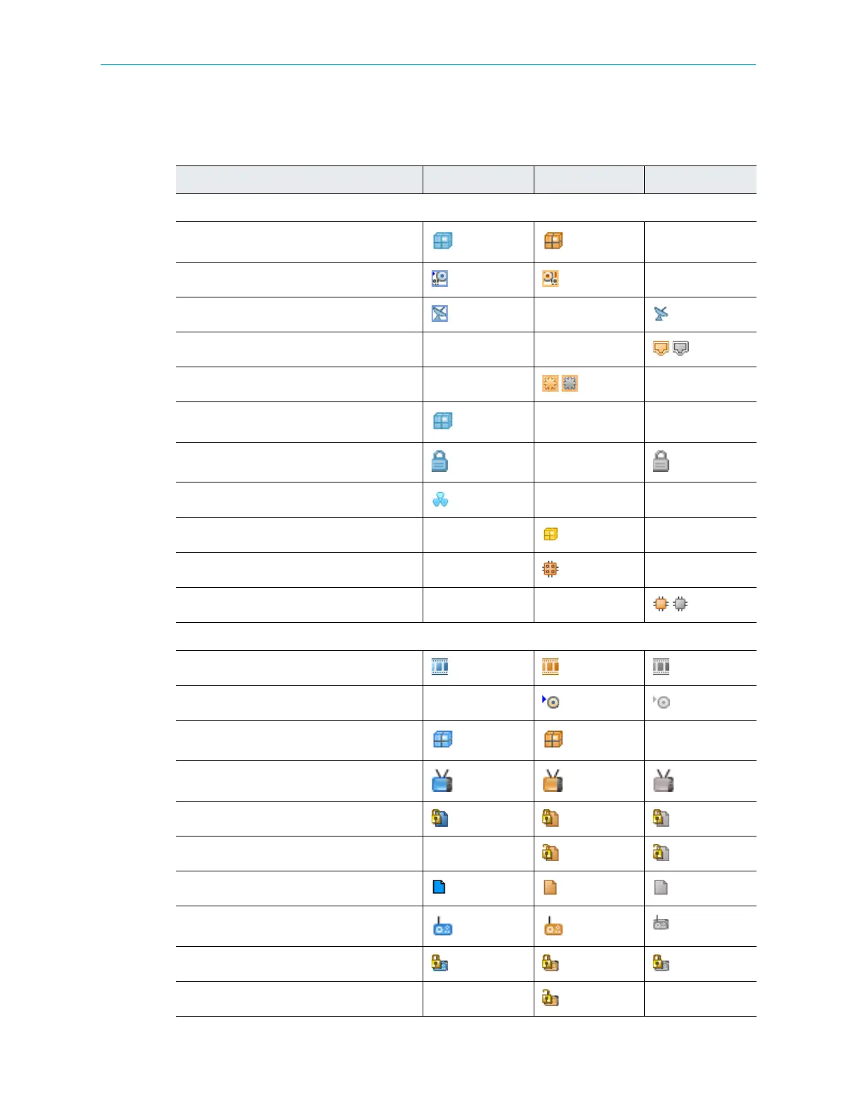
The ProView 7000 EMS GUI uses a wide range of icons to identify elements displayed on the
Device Explorer tab. The following table describes these icons.
Table 4–8: Device Explorer Icons
Icon Description In Out Disconnected
Physical Input/Output Icons
Port Holder
ASI Physical Port
DVB Physical Port
GbE Port
GbE Socket
CAMs Holder
CAM Slot
(card inserted) (no card)
CAM Card
Decoder Module
Decoder Card
Decoder Output
Multiplexing In/Out Icons
Multiplexed Port
TS Port Route
Programs Holder
Program
Scrambled Program
Descrambled Program
Data Type Program
Radio Type Program
Scrambled Radio Program
Descrambled Radio Program