,
3HONDA
!&
CM400T.400A
'80
ADDENDUM
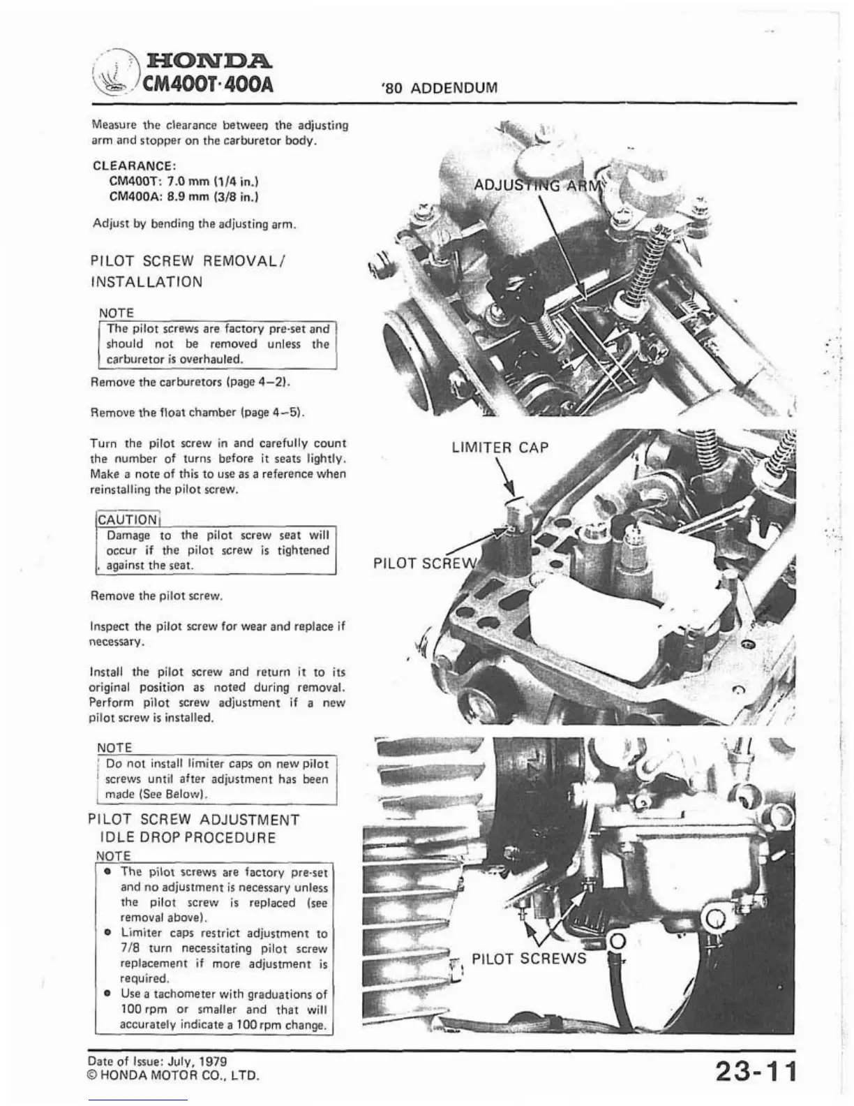
Measure the clearance betweeo the adjusting
arm and stopper on the carburetor body.
CLEARANCE:
CM4OOT: 7.0
mm
(114
in.)
CM400A:
8.9
mm
(318
in.)
Adjust by bending the adjusting arm
PILOT SCREW REMOVAL1
INSTALLATION
should not be removed unless the
Remove the carburetors (page
4-2).
Remove the float chamber lpage
4-5)
Turn the pilot screw in and carefully count
the number of turns before
it
seats lightly.
Make a note of this to use as a reference when
reinstalling the pilot screw.
CAUTION1
Damaoe to the ~ilot screw seat will
1
occur-if the pi~dt screw
is
tightened
,
against the seat.
Remove the pilot screw.
Inspect the pilot screw for wear and replace if
necessary.
Install the pilot screw and return
it
to
its
original position as noted during removal.
Perform pilot screw adjustment if a new
pilot screw
is
installed.
NOTE
i
DO not install limiter caps on new pilot
!
screws until after adjustment has been
I
made (See Belowl.
PILOT SCREW ADJUSTMENT
IDLE DROP PROCEDURE
The pilot screws are factory pre-set
and no adjustment is necessary unless
the pilot screw is replaced (see
removal above).
Limiter caps restrict adjustment to
718
turn necessitating pilot screw
replacement if more adjustment is
required.
Use a tachometer with graduations of
lOOrpm or smaller and that will
accurately indicate a
l00rpm change.
EN
Date of Issue: July.
1979
O
HONDA MOTOR
CO..
LTD.