H-S81-HS Installation & Operation Manual — P/N LS10114-000HI-E:A 2/24/2015 105
Section 3: Installation
This chapter provides all the necessary information for proper product installation.
3.1 Positioning of the Control Panel
Before positioning the H-S81-HS control panel, please refer to the environmental specifications for
proper product operation described in Section 1.3. The control panel must be located in a properly
monitored area and in a place granting easy access to the staff.
3.2 Measures for Installation in Compliance with the EC
Standard
For proper system installation on the steelwork, undertake the following measures:
• Use only power supply sets certified for the product.
• Lay power cables and terminating cables of field devices on two separate paths.
• Use shielded cables to connect field devices and I/O modules.
• Follow all the instructions provided for system earthing.
• In case of permanent installation, the electrical system of the building must be provided with a
(magnetothermal/differential) disconnect device, easy to be accessed and with the following
features:
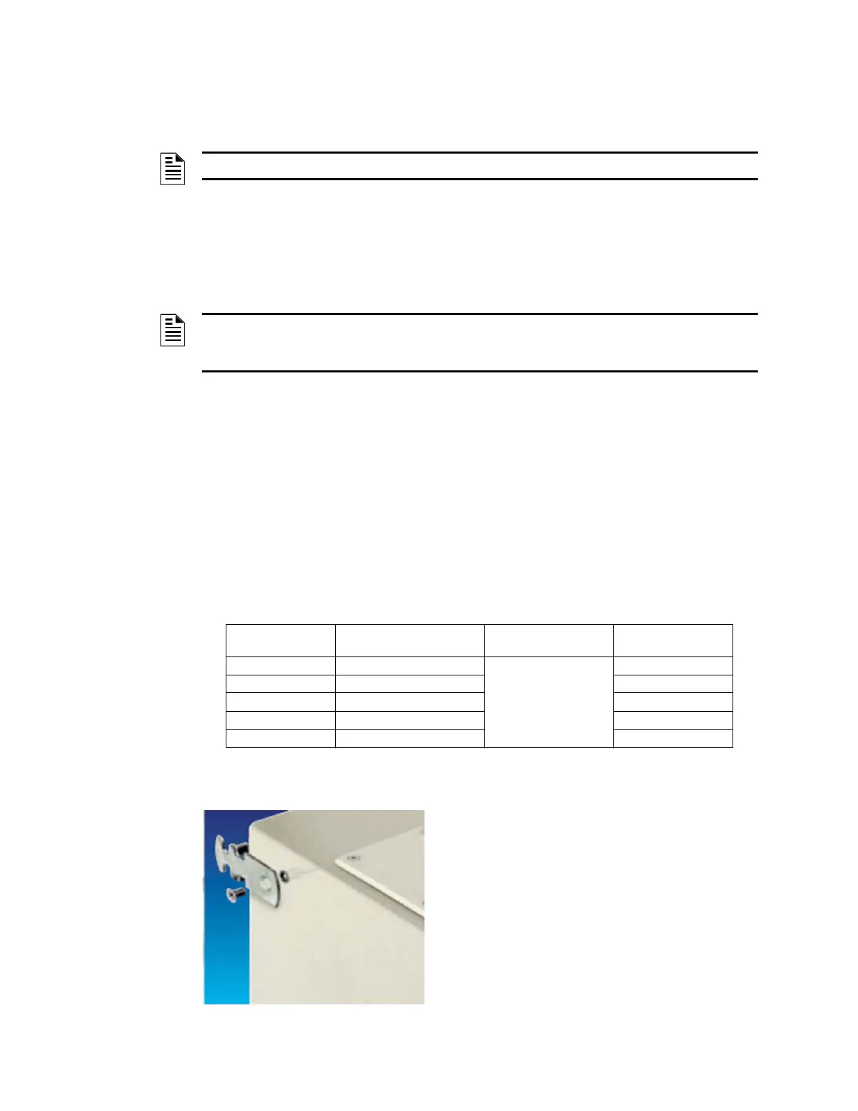
3.3 Mounting the H-S81-HS-1R & H-S81-HS-2R Control Panels
The control panel must be located in an easily accessible
place, well signaled and protected against fire. To mount
the steelwork to the wall (H-S81-HS-1R, H-S81-HS-2R)
use the four tabs provided. To mount it to masonry walls,
use Fisher-like nylon expansion anchors of at least 8mm.
NOTE: All operations described in this chapter must be carried out by certified personnel.
NOTE: All the parts used in H-S81-HS systems are selected depending on the relevant intended
use and are suitable for operating in compliance with the technical specifications and the relevant
environmental conditions therein specified.
Power Supply Set
Max. Absorbed Current at
110VAC
Type of Protection
Electrical
Characteristics
S81-PU001-1 1.6A
Magnetothermal
differential switch
6A-400VAC
S81-PU001-2 3.3A 10A-400VAC
S81-PU001-4 6.4A 12A-400VAC
S81-PU002-2 6A 12A-400VAC
S81-PU002-4 12A 20A-400VAC
 Loading...


