H-S81-HS Installation & Operation Manual — P/N LS10114-000HI-E:A 2/24/2015 99
Termination modules Parts of the H-S81-HS System
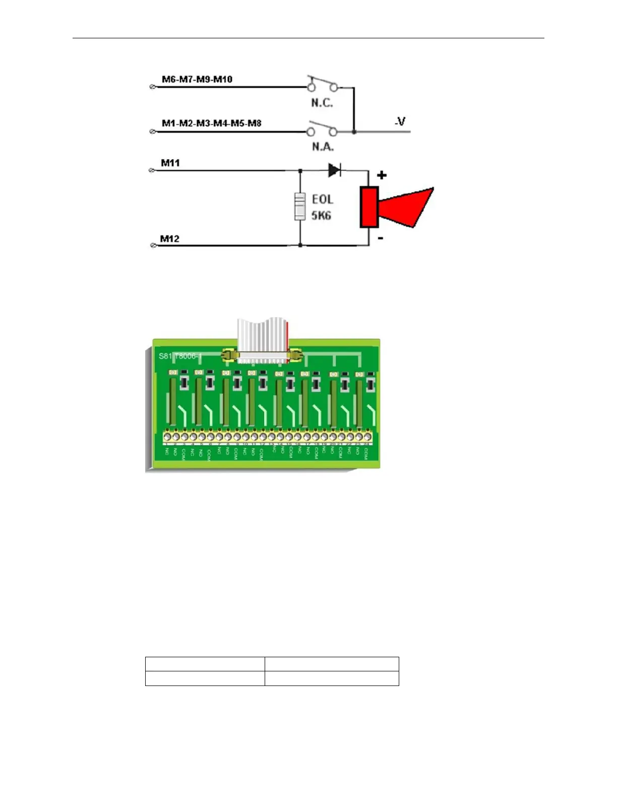
Standard Connection Diagrams
2.5.6 S81-T8006-1
Description
It is used with S81-E2001-1 type
buses to terminate S81-F5001-1 mod-
ules. It features 8 x SPDT output con-
tacts to connect SELV circuits only.
Technical Features
Status Indications
The module includes 8 green LEDs for relay status indication:
Figure 2.48 – Inputs and Local Sounder Output Standard Connection Diagram
• Supply voltage: 22-29VDC
• Quiescent current: 0mA
• Contact type: SPDT
• Contact capacity: 4 A 30VDC
• Assembly: on DIN bar
• Operating temperature: -5 - 50 °C
• Storage temperature: -30 - 80 °C
• Maximum humidity: 95% (RH) non-condensing
• Dimensions: W 135 x H 77 x D 50 mm
LED Condition
LED1 - LED8 (Green LEDs) It lights up when relay coil is active
 Loading...


