H-S81-HS Installation & Operation Manual — P/N LS10114-000HI-E:A 2/24/2015 107
Layout of H-S81-HS/1R Internal Parts Installation
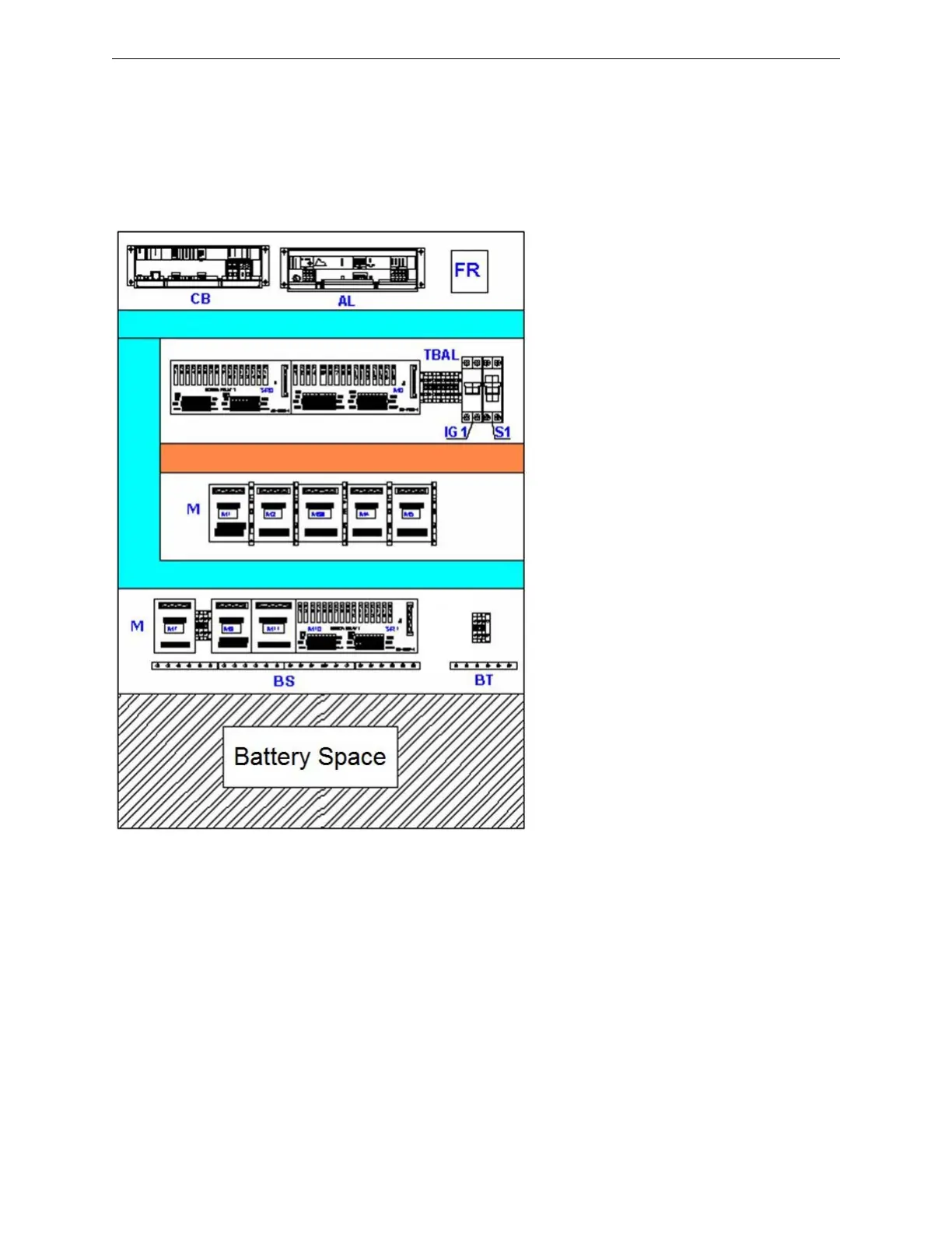
3.5 Layout of H-S81-HS/1R Internal Parts
The picture below shows the typical layout of the parts located on the base plate of H-S81-HS/1R
type control panels. In this specific configuration, field device cables are connected to I/O modules
with termination modules or multi-conductor cables. Light blue cable trays are only for cables con-
necting I/O racks to termination modules. The orange cable tray instead is only for cables coming
from field devices.
• CB PU-A0004-1 Battery Charger
• AL PU-A0005-1 Power Supply Unit
• FR Network Filter
• TBAL 25VDC Power Supply Distribution
• IG1 Main Switch
• S1 Battery Disconnect Switch
• M Termination Modules
• BS Earth Bar of Shields
• BT Safety Earth Bar
Figure 3.4 H-S81-HS/1R Internal Plate
 Loading...


