46 H-S81-HS Installation & Operation Manual — P/N LS10114-000HI-E:A 2/24/2015
Parts of the H-S81-HS System I/O modules
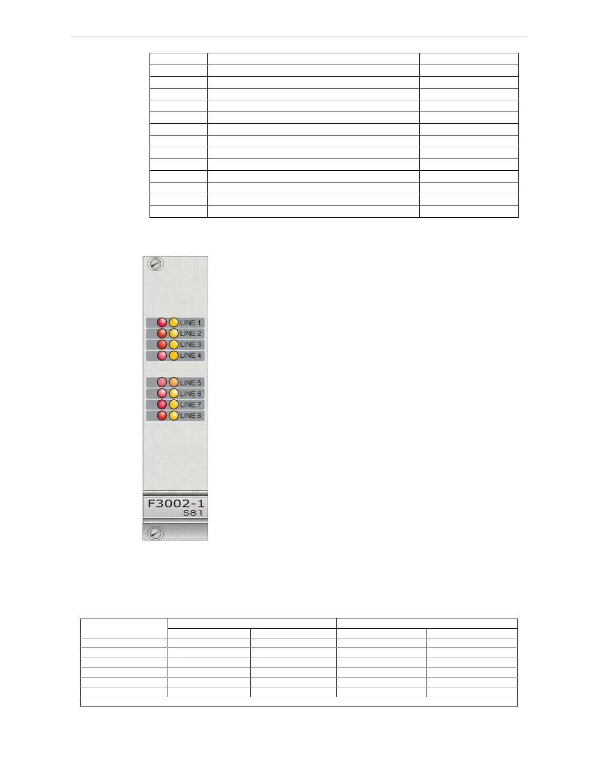
2.4.1 S81-F3002-1 & S81-F3002-2
Description
Eight balanced input module for conventional safety related sensors. All chan-
nels can be reset individually and are tested every 30 seconds during operation.
This module is suitable for controlling detection systems with conventional
lines and can be used in systems with already existing detection lines for con-
trolling automatic fire extinguishing systems with double enable logic or intrin-
sically safe systems. It is also used for controlling all the devices typical of fire
extinguishing systems (pressure switches, discharge buttons, etc.). This module
can be duplicated in fault tolerant systems; in this case, the two modules shall
be placed on adjacent racks in the same position. In this configuration, the eight
detection lines are connected to both modules.
Technical Features
Status Indications
Each one of the eight channels on the front panel includes two status LEDs providing the following
information:
S81-F5001-1 Module with 8 x 500mA monitored outputs for solenoids Redundancy not possible
S81-F5001-2 Module with 8 x 500mA monitored outputs for solenoids Redundancy possible
S81-F5002-1 Module with 16 x 250mA non monitored outputs Redundancy not possible
S81-F5003-1 Module with 8 x 250mA monitored outputs for sounders Redundancy not possible
S81-F5004-1 Module with 4 x 2A monitored outputs for solenoids Redundancy not possible
S81-F5004-2 Module with 4 x 2A monitored outputs for solenoids Redundancy possible
S81-F6001-1 Module with 8 outputs for fire extinguishing system control Redundancy not possible
S81-F6002-1 Logic module Redundancy not possible
S81-F7002-1 Loop control module with ESP protocol Redundancy not possible
S81-F7006-1 Modbus RTU Master/Slave module Redundancy not possible
S81-F7007-1 Loop control module with SSP protocol Redundancy not possible
S81-F7008-1 Control modules for weighing modules Redundancy not possible
S81-F7009-1 Loop control module with XP95/Discovery protocol Redundancy not possible
S81-F7010-1 Loop control module with System Sensor protocol Redundancy not possible
• Safety rating: applicable up to SIL3
• Redundancy: S81-F3002-2 model
• Alarm threshold: 2 programmable thresholds on 255 levels
• Line short circuit current >115mA
• Channel test: every 30 seconds
• Intrinsic Safety Barriers allowed: uZ680+ Pepperl & Fuchs
• Supply voltage: 22-29VDC
• Quiescent current: 14mA
• Operating temperature: -5 - 50 °C
• Storage temperature: -30 - 80 °C
• Maximum humidity: 95% (RH) non-condensing
• Hot swap capability: yes
Input channel status
Indications Line LEDs 1-8 in SAFETY mode Indications Line LEDs 1-8 in SECURITY mode
Yellow LED Red LED Yellow LED Red LED
Normal −− − −
Disabled ⊗− ⊗ −
Trouble ∅− ∅ −
Tampering −−− −−− − ∅
Pre-alarm −∅−−−−−−
Alarm −⊗ − ⊗
Key to symbols: ⊗= steady on LED; − = LED off, ∅= flashing LED, −−−= function not available
 Loading...


