H-S81-HS Installation & Operation Manual — P/N LS10114-000HI-E:A 2/24/2015 49
I/O modules Parts of the H-S81-HS System
2.4.2 S81-F4001-1 & S81-F4001-2
Description
Safety related module with 1 x 4-20mA analog input and two programmable
thresholds. It can control the following transducer types: explosion sensors, air
quality sensors, oxygen sensors, temperature sensors, 4-20mA general sensors.
The channel is continuously tested during operation. The module features a 4-
20mA output that provides the current value measured on the input. This analog
value can be transferred to a DCS by means of the S81-F7006-1 Modbus RTU
module. This module can be duplicated in fault tolerant systems; in this case, the
two modules shall be placed on two adjacent racks in the same position. In this
configuration, the detection lines is connected to both modules.
Technical Features
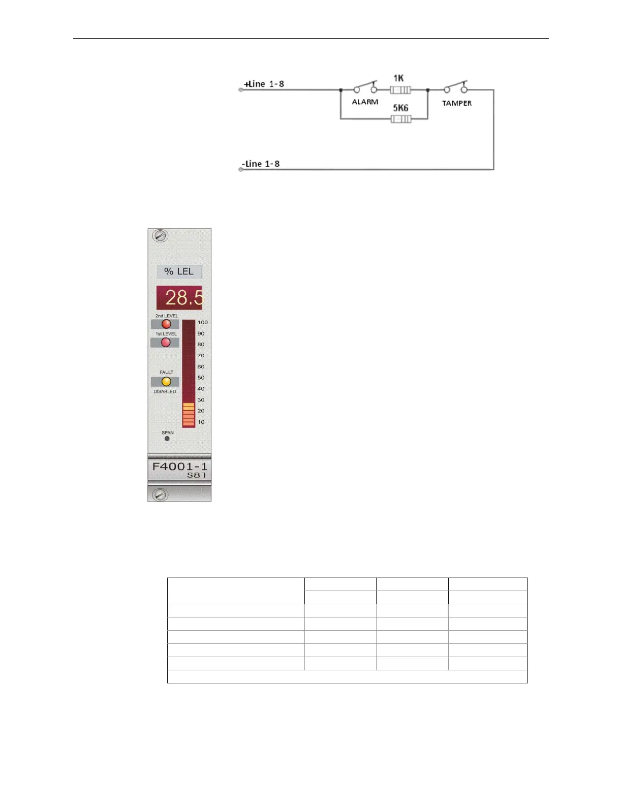
Status Indications
Module front panel includes three LEDs, a graphic LED bar, and a three-digit display.
LED Bar
It indicates the 0-100% percentage of the measured value.
Figure 2.20 Standard Connection Diagram for Burglar Alarm
• Safety rating: applicable up to SIL3
• Redundancy: S81-F4001-2 model
• Alarm threshold: 2 programmable thresholds
• Channel test: continuously tested
• Measuring range 0-24mA
• Line short circuit condition: with current >23.5mA
• Supply voltage: 22-29VDC
• Quiescent current: 35mA
• Operating temperature: -5 - 50°C
• Storage temperature: -30 - 80°C
• Maximum humidity: 95% (RH) non-condensing
• Hot swap capability: yes
Input channel status
2nd Level 1st Level Fault/Disabled
Red LED Red LED Yellow LED
Normal −− −
Disabled −− ⊗
Trouble −− ¬
Pre-alarm ⊗⊗ −
Alarm ⊗− −
Key to symbols: ⊗= steady on LED; − = LED off; ∅= flashing LED
 Loading...


