172 H-S81-HS Installation & Operation Manual — P/N LS10114-000HI-E:A 2/24/2015
Power Supply Set Dimensions External Load Absorption
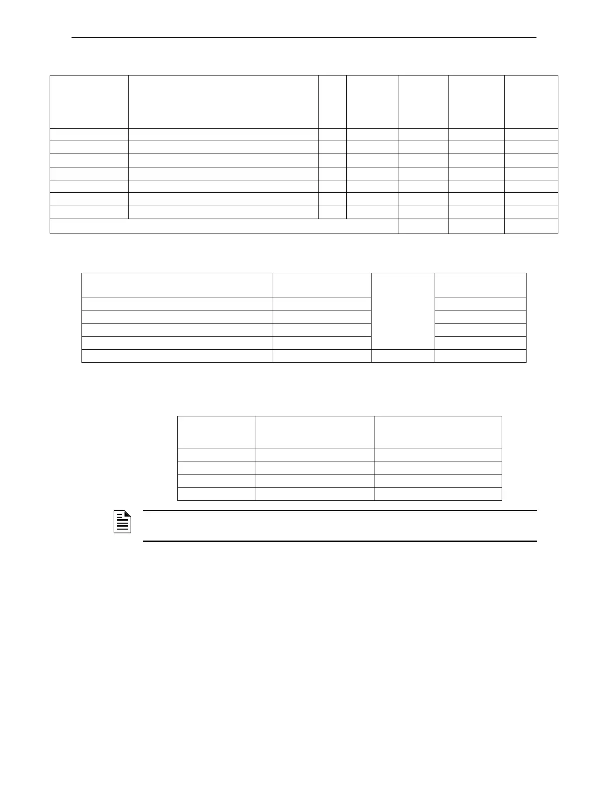
C.7 External Load Absorption
C.8 Calculation of Total System Absorption
The table below indicates the power supply sets that can be used according to the total alarmed sys-
tem current calculated.
C.9 Calculation of Battery Capacity
According to the European and US standards, the operating time of H-S81-HS control panel with
primary voltage failure is:
• Standby: 24 h
• Alarm: 5 minutes = 0.083 h
Part Number Description Qty.
Quiescent
current
Total
quiescent
current
Current with
alarmed
control panel
Total
current with
alarmed
control
panel
Visual and audible alarm devices
Solenoids
Magnets
Gas detectors
Flame detectors
Replication relays
Other loads
Total quiescent current (A7) Alarmed (B7)
Description Total quiescent current
Total current with
alarmed control panel
H-S81-HS control panel absorption (A1) (B1)
Max. sensor absorption (A2) (B2)
Absorption of Addressable Devices (A3+A4+A5+A6) (B3+B4+B5+B6)
Absorption of External Loads (A7) (B7)
Total quiescent current (A8) Alarmed (B8)
Total current with
alarmed control
panel
Power supply sets to be used
in mono configuration
Power supply sets to be used in
duplex configuration
<4A S81-PU001-1 S81-PU001-2, S81-PU002-2
<8A S81-PU001-2 S81-PU001-4, S81-PU002-2
<16A S81-PU001-4 S81-PU002-2
<20A N/A S81-PU002-4
NOTE: Use the suitable power supply set according to the total current calculated with alarmed
system.
 Loading...


