42 H-S81-HS Installation & Operation Manual — P/N LS10114-000HI-E:A 2/24/2015
Parts of the H-S81-HS System I/O Rack
Internal connections
BR1 & BR2: +V/-V
These two Faston terminals are used for supply voltage connection
J2
A connector for 20-pole flat cable, allowing the connection to S81-E2003-1 Bus module.
J3
A 4-pole connector supplying power to the LEDs for display backlighting.
J5
A 10-pole connector connecting the membrane keyboard to the display.
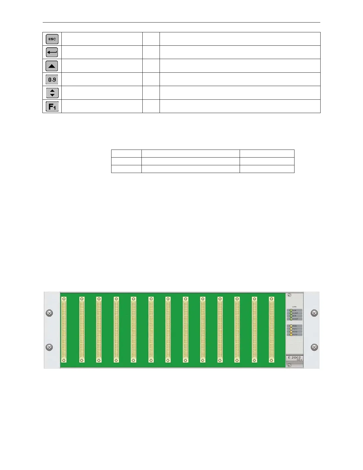
2.3 I/O Rack
Up to ten expansion racks can be connected to an H-S81-HS base. Each can include up to thirteen
I/O modules. Position 14 is reserved to the S81-E2002-1 rack controller. Two I/O rack types are
available according to the type of terminations to be used.
Selection cancel 1-2-3 To cancel an operation or to go back to the previous page
Enter key 1-2-3 Confirms a selection made when navigating through operator cycle menus
Arrows for selecting menu direction 2-3 They enable the navigation through operator cycle menus
0-9 key numbers 1-2-3 They are used for entering parameters and access passwords
Scroll 1-2-3 It allows to view the complete list in operator cycle menu
F1 key 1-2-3 It allows to access directly the main page of the active access level
TAG Function Cable Color
BR1 25VDC power supply positive Red
BR2 25VDC power supply negative Black
Figure 2.11 I/O Rack - Front View
 Loading...


