48 H-S81-HS Installation & Operation Manual — P/N LS10114-000HI-E:A 2/24/2015
Parts of the H-S81-HS System I/O modules
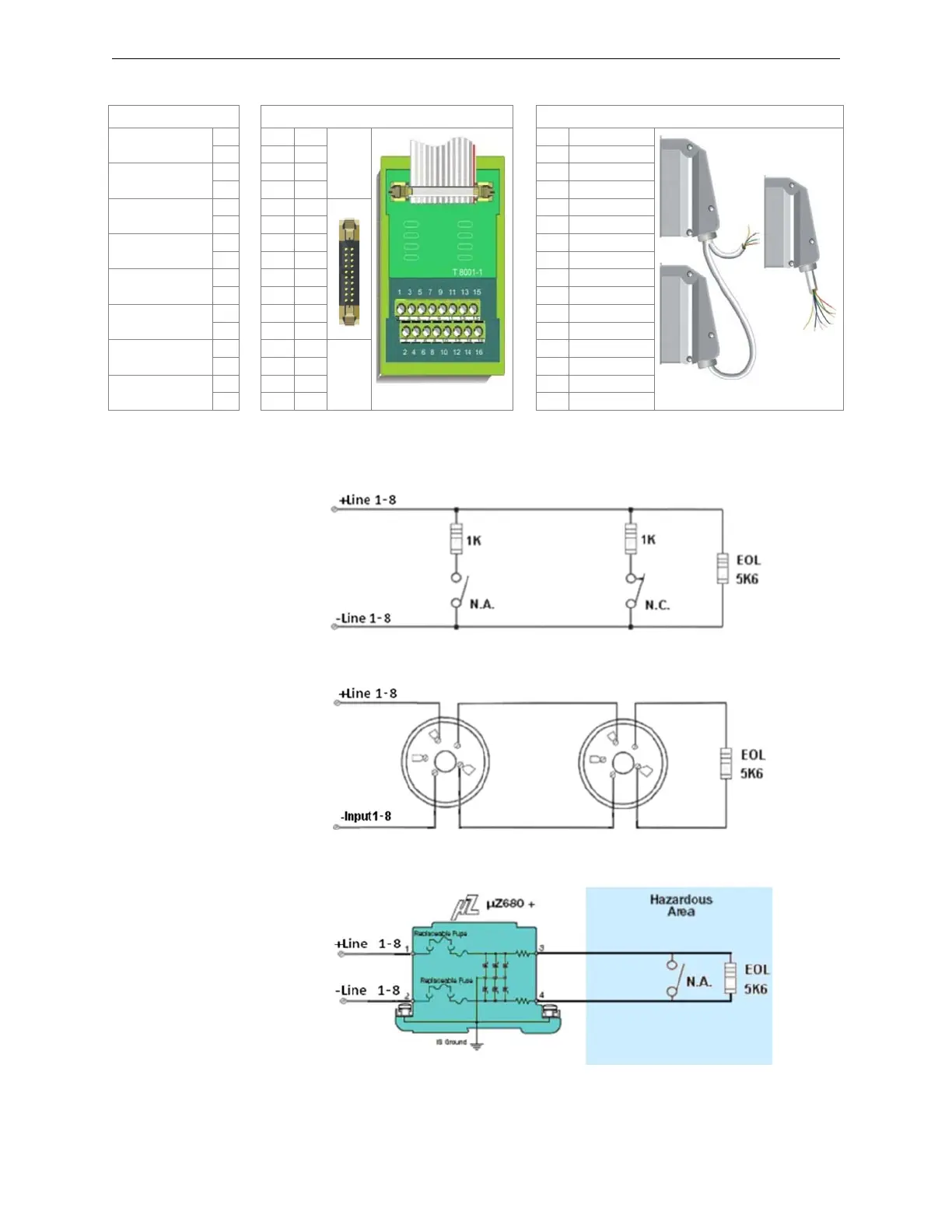
Standard Connection Diagrams
Function Termination with Flat Cable Termination with Multi-conductor Cable
detection line 1
+ ∅ 1
T8001
terminals
S81-T8001-1
1White
- ∅ 22Brown
detection line 2
+ ∅ 3 3 Green
- ∅ 44Yellow
detection line 3
+ ∅ 55Gray
- ∅ 66Pink
detection line 4
+ ∅ 77Blue
- ∅ 88Red
detection line 5
+ ∅ 99Black
- ∅ 10 10 Violet
detection line 6
+ ∅ 11 11 Gray/pink
- ∅ 12 12 Red/blue
detection line 7
+ ∅ 13
Rack - rear
view
13 White/green
- ∅ 14 14 Brown/green
detection line 8
+ ∅ 15 15 White/yellow
- ∅ 16 16 Yellow/brown
Figure 2.16 Field connections
Figure 2.17 Standard Connection Diagram of NO/NC Contacts
Figure 2.18 Standard Connection Diagram of Conventional Detectors
Figure 2.19 Standard Connection Diagram of the Intrinsic Safety Barrier
 Loading...


