64 H-S81-HS Installation & Operation Manual — Form Number XX-XXXX—X P/N LS10114-000HI-E:A 2/24/2015
Parts of the H-S81-HS System I/O modules
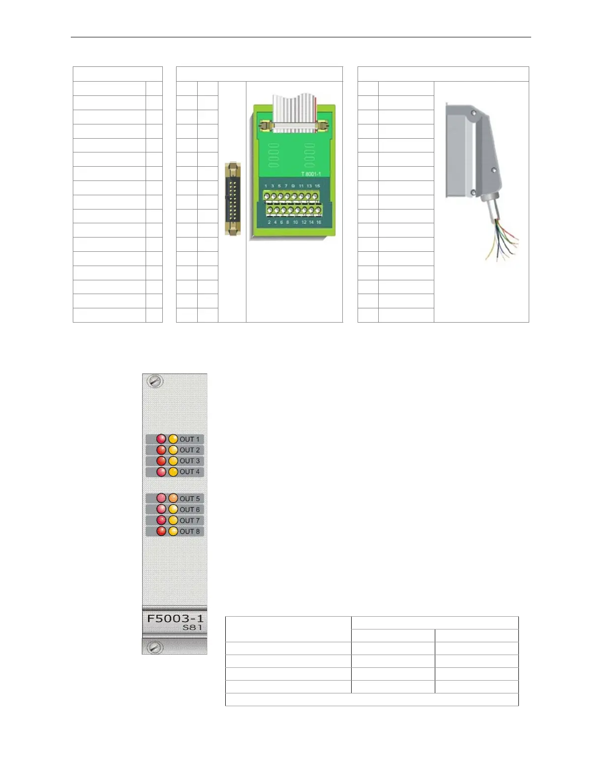
2.4.7 S81-F5003-1
Description
Module with 8 x 250 mA monitored output channels for sounder control. Outputs
are controlled by two virtual channels for allowing both continuous and intermit-
tent output control. Line is monitored by polarity reversal.
Technical Features
Status Indications
Each one of the eight channels on the front panel includes two status LEDs.
Function Termination with Flat Cable Termination with Multi-conductor Cable
Output 1
- ∅ 1
S81-T8001-1
1
White
S81/CCT1
Output 2
- ∅ 22
Brown
Output 3
- ∅ 33
Green
Output 4
- ∅ 44
Yellow
Output 5
- ∅ 55
Gray
Output 6
- ∅ 66
Pink
Output 7
- ∅ 77
Blue
Output 8
- ∅ 88
Red
Output 9
- ∅ 9
Black
Output 10
- ∅ 10
Violet
Output 11
- ∅ 11
Gray/Pink
Output 12
- ∅ 12
Red/Blue
Output 13
- ∅ 13
White/Green
Output 14
- ∅ 14
Brown/Green
Output 15
- ∅ 15
White/Yellow
Output 16
- ∅ 16
Yellow/Brown
Common Positive
+
White/Gray
Figure 2.29 Field Connections
• Redundancy: No
• Channel test: No
• Max. output current 250mA
• Automatic output protection: Yes
• Supply voltage: 22-29VDC
• Quiescent current: 38mA
• Operating temperature: -5 - 50 °C
• Storage temperature: -30 - 80 °C
• Maximum humidity: 95% (RH) non-condensing
• Hot swap capability: yes
Output channel status
Indications 1 - 8 Out LEDs
Yellow LED RED LED
Off −−
Disabled ⊗−
Trouble ∅−
Active −⊗
Key to symbols ⊗= steady on LED; − = LED off; ∅= flashing LED
 Loading...


