40 H-S81-HS Installation & Operation Manual — P/N LS10114-000HI-E:A 2/24/2015
Parts of the H-S81-HS System Central Unit Rack
Status Indications
The module front panel includes four LEDs indicating the following conditions:
Connections
On module front panel there is an 8-pole RJ45 connector, enabling module connection to the Ether-
net network. Through this port, connections with maximum length of 100 mm can be carried out
using category 5 cables.
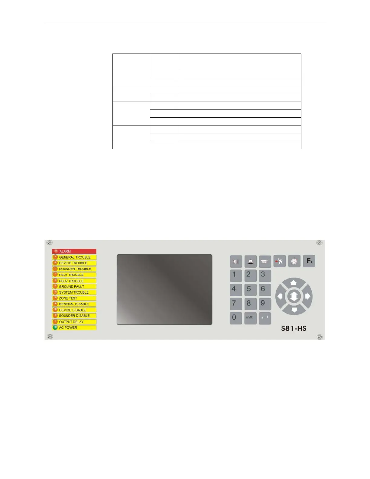
2.2.3 S81-U1006-1
Description
The display module is the interface between the control panel and the operator. It includes a LED-
backlit graphic display with 30 lines of 52 characters each, 19 LEDs, 23 buttons, and one buzzer.
LED Mode Indication
Link
(Green)
⊗
Ethernet connection link present
−
No Ethernet connection link
Activity
(Green)
∅
Data transmission/receipt on the Ethernet port
−
No activity on the Ethernet port
Run
(Green)
⊗
Primary CPU
∅
Secondary CPU
−
Blocked CPU
Wdo
(Yellow)
−
Operating CPU
⊗
Blocked CPU
∅ = flashing ⊗ = steady on − = off
 Loading...


